Getting Started
The radar client interface that vice provides is based on STARS.
For familiarity to VATSIM controllers, vice generally follows the keyboard command scheme implemented
in CRC's STARS implementation; see
the discussion of vice's STARS
emulation below for more information.
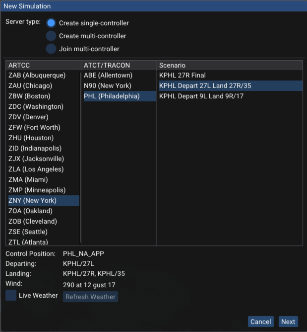
The first time you launch vice, a window is shown for configuring the simulation.
(After the first time, the window can be brought up by clicking the "replay" button in the menubar: .)
A number of scenarios are available, some departure-only and
some including both departures and arrivals.
Here is an example:
After selecting an ARTCC, the available TRACONs and ATCT/TRACONs in that ARTCC are shown.
Selecting one of those gives a number of scenarios to choose from. Here the ZNY ARTCC has
been selected and then the PHL ATCT/TRACON. After choosing a scenario and clicking the "Next"
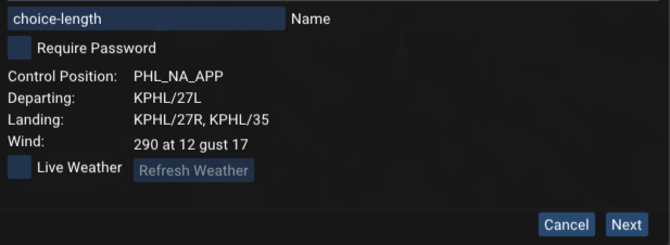
button, a window with further settings is shown:
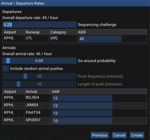
In the second configuration window, you can specify your initials, used to identify yourself to other
controllers, as well as various additional settings.
You can also adjust how heavy the traffic is; here, the departure rate settings are shown.
(The PHL scenario only includes the Philadelphia Airport, though many other scenarios include multiple airports.)
These rates are specified in terms of aircraft per hour, so an ADR of 30 corresponds to one aircraft departing
every two minutes (on average).
If you'd like an arrival-only scenario, for example, just set all of the departure rates to zero.
For arrivals, the "Go around probability" slider allows setting the probability that each arrival goes around.
You may also select "Include random arrival pushes", which will periodically bump up the rate of
arrivals to increase the challenge of vectoring aircraft.
"Push frequency" sets how often arrival pushes happen and "Length of push" sets how long they last
before traffic returns to regular levels.
After you have configured the simulation, click "Create" and you will have a STARS scope and flight strip window to work with.
Use the usual STARS commands as appropriate (to initiate track, accept handoffs, handoff to other controllers, etc.),
and the additional ATC commands below to issue control commands to aircraft.
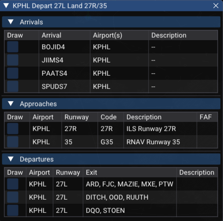
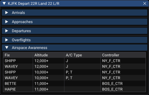
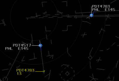
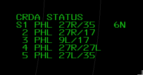
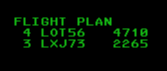
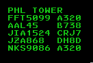
After the simulation starts, you may click on the button in the menubar to show
a window with information about the scenario, including the active controllers, the departures, arrivals, approaches and
overflight routes, and airspace awareness rules.
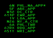
For this PHL scenario, four arrivals, two approaches, and three departures are active.
Other scenarios may be more complex.
The approach codes—here, "27R" and "35"— are used in vice's aircraft control commands like "expect approach"
and "cleared approach".
To adjust the amount of space used for flight strips, right click the line separating the flight strips from the
radar window and drag left or right with your mouse.
You can also remove flight strips entirely by opening the settings window, in the menubar, and disabling "Show flight strips" under the "Flight strips" header.
A number of buttons are available in the menu bar at the top of the window:
- / : pause or resume the simulation.
- : opens the window to select a new scenario and set its parameters.
- : open a window that allows changing various settings. The most useful one is the simulation rate: you can speed up time during slow times or to increase the challenge.
- : show the
window that lists the currently active departures,
arrivals, and approaches.
- : opens a window that
shows a summary
of vice's ATC commands
and frequently-used STARS commands.
- : open a window with controls for launching aircraft, either automatically or manually.
- : open this webpage to review vice's documentation.
- : display information about the version of vice you have installed.
- : join the vice Discord.
- : Toggle full-screen mode.
When you exit vice, it remembers everything going on—all of the aircraft in flight, the instructions they have been given, etc.
The next time you launch vice, it loads all of that back in and you can continue where you left off.
If you'd like to start something new, just click and configure a new simulation.
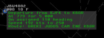
When vice is paused, you can hover the mouse above a radar track to see information about the instructions the aircraft has been given so far—for example, altitude and speed assignments, whether it has been sent direct to a fix, the approach it has been assigned, etc. An example is shown below. This information is especially useful when resuming a vice session after you have been away from it for a while.
If you are signed in to Discord, vice can
automatically update your activity status there with
information about your current vice session (the number
of arrivals and departures, the position you're controlling,
etc.) When you first launch vice you are given the
option to disable this feature if you would like. The
settings window, available by clicking in the menubar, can also be used to enable or
disable this feature.
Drawing Routes
vice can draw the active departures, approaches, and
arrivals for the current simulation. This can be helpful when
studying those for an airport, since they are drawn directly on
the radar scope with annotations that give the fixes, any
altitude or speed restrictions, and procedure turns.
To toggle whether a route is drawn on the scope, click the checkbox on the left
next to it in the information window that is shown at
the start or after clicking on the
button in the menubar.
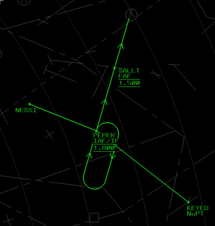
For example, here is how the HVN RNAV Runway 2 approach is rendered:
We can see the procedure turn at PEPER and that it is both
the IAF and the IF; altitude restrictions at both SALLT and
PEPER, that SALLT is the FAF, and that arrivals from KEYED will not fly the procedure
turn.
Launching Aircraft
When a new simulation starts, vice automatically launches new departures and arrivals based on the
departure and arrival rates set in the "New Simulation" window.
During a simulation, clicking on the departing plane icon in the menubar
opens a window that allows more control over aircraft launches and also for issuing releases for airports
where "hold for release" is in effect.
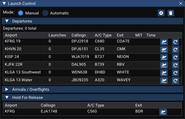
The rates for automatic launches can be adjusted in this window. Alternatively, aircraft can be launched manually. If manual launches are selected,
the window shows all of the available departure runways and exits as
well as all of the arrivals, as shown below. Clicking the aircraft icon for a departure or arrival
causes the aircraft shown to be launched. If you'd like a different aircraft for the
next launch (for example, to have a heavy aircraft), click the redo icon until you're happy with the selection.
The window also shows the elapsed time since the launch of each type as well as how many
miles in trail (MIT) there would be if the next aircraft was launched.
To delete all of the aircraft from the simulation and restart, click the trash icon:
.
Multiple Controllers
With vice you can also have multiple controllers working aircraft together.
Select "Create a sim on the public vice server" in the "New Simulation" window and
you can select an ARTCC, ATCT/TRACON, and scenario in the same way
that you do with a single controller.
For multi-controller scenarios, there are some additional settings, shown beneath
the list of scenarios:
If you sign in with instructor/RPO (remote pilot operator) privileges, then
you are able to issue control instructions to all aircraft.
Each multi-controller simulation also has a name associated with it;
vice chooses a random one (above, it's "plenty-manufacturer").
These names can be used so that you can tell other people which
simulation to choose in order to join you.
You may also enable "Require password" and enter a password for the
simulation so that only people you allow can join it.
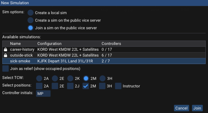
Selecting "Join a sim on the public vice server" shows a list of the simulations
that are currently available, including how many controllers
are signed into each one.
Note that the simulation names are shown in the first column.
After selecting one, the currently unoccupied radar workstations (TCWs)
are shown, though if you select "Join as relief", you may connect to
a TCW that is already in use; this allows relieving another controller,
who may then disconnect after briefing you.
After selecting a TCW, you can select one or more terminal control positions (TCPs)
that you will be responsible for; your TCPs determine the airspace and which
handoff flows are your responsibility.
vice also allows you to join a simulation as an observer,
in which case you have no control capabilities; to do so, select a free TCW
and then do not select any TCPs.
ATC Instructions (Keyboard)
A variety of instructions can be issued to aircraft by an aircraft controller.
To issue an instruction, first press the [TAB] key.
This will place the STARS radar into "target generation" mode and the characters "TG"
will appear above the text input area (which is by default on the left side of the STARS
window, towards the top. STARS reverts to normal command entry mode after a valid ATC
instruction is entered, though target generation can be locked by pressing [SHIFT][TAB].
The commands below can then be entered to issue control commands to aircraft.
As you enter commands, they will be shown in the STARS input area.
You can correct errors with the backspace key or press the [ESCAPE] key
to exit target generation mode.
To indicate which aircraft should be given a command, you
can either enter a command and click on an aircraft's radar
track in the STARS window or you can enter the aircraft's callsign followed by a space
before the command, and then press the "enter" key. You can also give just the callsign suffix,
if that is enough to unambiguously identify a single aircraft.
The callsign of the last aircraft you issued to a command to is shown after "TG" when
target generation mode is activated.
If you'd like to give another instruction to that aircraft, you can skip entering its callsign.
Entering another aircraft's callsign causes the command to be issued to that aircraft instead.
After you issue a command, the virtual pilot's readback is
shown in the readback window below the STARS window.
After receiving an instruction, the aircraft will start
following that instruction, to the best of its abilities.
Unlike VATSIM, the pilots will always do exactly what you
tell them to.
If you'd like to issue multiple commands to an aircraft at once,
enter the commands one after another with a space between them.
To open a window that shows the available ATC commands when using vice,
click the button in the top menubar.
The following commands relate to the aircraft's lateral route:
| Command |
Function |
Example |
Hheading |
Directs the aircraft to fly the specified heading. It will turn in whichever direction gets it to that heading most quickly.
If no heading is given, the aircraft is instructed to fly present heading. |
H050, H |
Lheading |
Directs the aircraft to turn left to the specified heading. |
L130 |
Rheading |
Directs the aircraft to turn right to the specified heading. |
R210 |
TdegreesL |
Directs the aircraft to turn the specified number of degrees to the left. |
T10L |
TdegreesR |
Directs the aircraft to turn the specified number of degrees to the right. |
T20R |
Dfix |
Directs the aircraft to proceed direct to the given
fix. (The specified fix must be in the aircraft's
flight plan, including on the approach assigned to it.) |
DWAVEY |
Dfix/Hheading |
Directs the aircraft to depart the specified fix at the given heading.
(The specified fix must be in the aircraft's flight plan.) |
DLENDY/H180 |
Hfix |
Directs the aircraft to hold at the specified fix using a published holding pattern.
(The specified fix must be in the aircraft's flight plan; for one that is not, first give them Dfix
to add it and send them direct to it.)
There are three ways to cause an aircraft to exit a hold:
1. Clearing them for the approach, if the hold is part of an approach assigned to the aircraft.
2. Giving "direct FIX".
3. Assigning a heading.
In the first two, the aircraft will finish flying the current lap in the hold before proceeding;
if a heading is given, they will turn to the heading directly.
|
HJIMEE |
Hfix/option/option |
Directs the aircraft to hold at the specified fix using controller-specified holding parameters.
(The specified fix must be in the aircraft's flight plan.)
Options may be:
L: left turnsR: right turns (default)- xx
NM: xx nautical mile legs
- xx
M: xx minute legs (default: 1 minute)
Rxxx: inbound course on the xxx radial to the fix (required)
The radial option (Rxxx) is required for controller-specified holds.
Multiple options of the same type (e.g., both L and R, or both distance and time legs) are not allowed.
|
HJIMEE/L/5NM/R090
HJIMEE/R270/2M |
SH |
Directs the aircraft to say its current heading. |
SH |
And these commands are related to altitude:
| Command |
Function |
Example |
Calt |
Directs the aircraft to climb to the specified
altitude, which is given in hundreds of feet.
If the aircraft is changing speed, both the speed
change and climb are simultaneous.
|
C170 |
TCalt |
Directs the aircraft to climb to the specified
altitude, given in hundreds of feet, after it
finishes speeding up or slowing down to meet a
controller-specified speed.
|
TC170 |
Dalt |
Directs the aircraft to descend to the specified
altitude, given in hundreds of feet. |
D20 |
TDalt |
Directs the aircraft to descend to the specified
altitude, given in hundreds of feet, after it
finishes speeding up or slowing down to meet a
controller-specified speed.
|
TD20 |
Aalt |
Directs the aircraft to maintain the given altitude given in hundreds of feet,
climbing or descending if necessary.
If the aircraft is changing speed, both the speed
change and climb are simultaneous.
|
A120 |
ED |
Directs the aircraft to expedite the descent to its
assigned altitude. |
ED |
EC |
Directs the aircraft to expedite the climb to its
assigned altitude. |
EC |
Cfix/Aaltitude/Sspeed |
Directs the aircraft to cross the specified fix at the given altitude and speed.
Either one or both of A
and S may be specified.
Altitudes may be given as single altitudes (corresponding to
"at"), an altitude and a plus sign ("at or above"),
an altitude and a minus sign ("at or below"), or a
range of altitudes separated by a minus sign ("between"). |
CCAMRN/A110+ |
CVS |
Directs a departure to "climb via the SID". |
CVS |
DVS |
Directs an arrival to "descend via the STAR". |
DVS |
SA |
Directs the aircraft to say its current altitude. |
SA |
These commands are for aircraft speed:
| Command |
Function |
Example |
Sknots |
Gives the aircraft a speed restriction.
If the restriction is given after an aircraft is cleared for an approach,
the speed restriction is in effect until 5 mile
final. If no speed is given, then the aircraft is instructed
"cancel speed restrictions". Speed changes happen at
the same time as any required altitude change. |
S210, S |
TSknots |
Gives the aircraft a speed restriction to be
applied after the aircraft climbs or descends to the
most recent controller-specified altitude.
As with S, speed restrictions are
canceled at 5 mile final. |
TS210 |
SMIN |
Directs the aircraft to maintain its slowest practical speed. |
SMIN |
SMAX |
Directs the aircraft to maintain its maximum forward speed. |
SMAX |
SPRES |
Instructs the aircraft to maintain its present speed. |
SPRES |
Skts+ |
Assigns a speed floor: aircraft should fly at or above the specified speed. Currently treated as a standard speed assignment. |
S180+ |
Skts- |
Assigns a speed ceiling: aircraft should not exceed the specified speed. Currently treated as a standard speed assignment. |
S180- |
SS |
Directs the aircraft to say its indicated airspeed. |
SS |
The transponder is managed using these commands:
| Command |
Function |
Example |
SQcode |
Instructs the aircraft to squawk the given beacon code. |
SQ1200 |
SQS |
Directs the aircraft to squawk "standby" mode. |
SQS |
SQA |
Directs the aircraft to squawk "altitude" mode. |
SQA |
SQON |
Directs the aircraft to turn on their transponder and squawk mode-A. |
SQON |
ID |
Instructs the aircraft to "ident". |
ID |
And these commands are instructions related to changing radio frequencies and contacting different controllers:
| Command |
Function |
Example |
FC |
"Frequency change": change radio frequency to the controller the aircraft was handed off to
and contact them. |
FC |
CTTCP |
Contact the controller with the specified TCP. This is generally used for VFR aircraft that contact
the wrong controller asking for flight following. |
CT2J |
TO |
Directs an arrival to contact the tower. |
TO |
A variety of commands are available related to approaches—specifying them and clearing aircraft for them.
| Command |
Function |
Example |
Eapproach |
Tells the aircraft to expect the specified
approach. This command must be used before an aircraft
is cleared for an approach and it also adds the approach
fixes to the end of the aircraft's route. |
EI2L |
Capproach |
Clears the aircraft for the specified
approach. The aircraft must have been told to expect the approach before it is cleared for it. |
CI2L |
C |
Clears the aircraft for the approach that was previously assigned. |
C |
Afix/C[approach] |
Clears the aircraft for the approach when
it passes the given fix. The approach identifier is optional;
if not specified, uses the previously-assigned approach. |
AROSLY/C |
Afix/I |
Directs the aircraft to intercept the localizer when
it passes the given fix. The aircraft must have been told
to expect an approach before this command is given. |
AROSLY/I |
CAC |
Cancels approach clearance for an aircraft. |
CAC |
CSIapproach |
Clears the aircraft "straight in" for the specified approach.
(This command is only useful for approaches that include procedure turns.)
The aircraft must have been told to expect the approach before it is cleared for it. |
CSII6 |
I |
Directs the aircraft to intercept the localizer (at
which point it will follow the localizer's lateral path
but not descend until it is cleared for the approach.) |
I |
For VFR aircraft that have been given vectors or altitude constraints, a few special instructions are available.
| Command |
Function |
Example |
A |
"Altitude your discretion, maintain VFR". |
A |
RON |
"Resume own navigation". |
RON |
RST |
"Radar services terminated, squawk VFR, frequency change approved". |
RST |
GA |
"Go ahead" - respond to a VFR request. |
GA |
Finally, a few miscellaneous commands are available.
| Command |
Function |
Example |
X |
Deletes the specified aircraft from the simulation. This command is useful when one starts going down the tubes. |
X |
P |
Toggles Pause/Unpause |
P |
Left Shift + Tab |
Toggles TGT GEN Lock |
Left Shift + Tab |
/message |
Displays the given message in the message log of all controllers |
/2A IS CLOSING DINNER TIME |
ATC Instructions (Spoken)
There is also support for issuing aircraft commands by speaking out loud (via
speech to text, or STT).
This is very much a work in progress but it is progressing quickly.
STT works best if you have a decent microphone and are not in a noisy environment
(music or TV in the background, etc.)
Results will generally be better if you have a discrete GPU in your computer (or
a laptop with a powerful laptop GPU); parts of STT run on the GPU and in able to
have good response times on machines with slower (or no) GPUs, we're able to do
less processing on spoken text and thus have more inaccurate transcriptions in
that case.
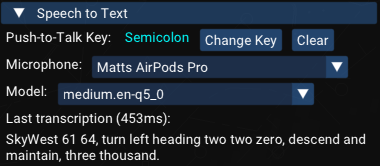
A few options related to STT may be controlled via the settings menu ( in the menubar):
It's important to make sure that the correct microphone is selected, if you have more than one (e.g. a headset and the built-in microphone).
By default, the push-to-talk key is ;, though this can be changed to another key.
The model allows selection of different speech-to-text transcription models; vice tries to choose one that gives
a reasonable balance of accuracy and speed for your system.
If you try a different model and are happier with the overall experience, please report your findings on the vice discord!
vice's STT system expects that proper (US FAA) phraseology will be used
to issue aircraft instructions, specifically Section 2-4: Radio and Interphone Communications for the basics and then other instructions as specified in the 7110.65.
It tries to be flexible to allow minor deviations
as are used in practice (as well as to allow errors in the STT transcription of the
audio), but if your phraseology is highly non-standard, you will likely not have
a good experience.
STT is also mostly limited to the control commands that vice supports in general
(i.e., those described in the previous section), though
there are a few commands that are STT-only. More details about expected phraseology
and supported commands in specific scenarios are in the following.
The following instructions are currently supported:
Altitude
| Type |
Phraseology |
| Assign Altitude |
Maintain (altitude) / Descend and maintain (altitude) / Climb and maintain (altitude) /
Altitude your discretion (for VFRs).
|
| Altitude at Fix |
Cross (fix) at (altitude) / Cross (fix) at or above (altitude)
|
| Altitude after Speed |
...then climb and maintain (altitude) / ...then descend and maintain (altitude), after a speed assignment—the aircraft will climb/descend after reaching the speed.
|
| Expedite Altitude |
Expedite descent / Expedite climb
|
| Say Altitude |
Say altitude
|
SIDs and STARs
| Type |
Phraseology |
| Climb/Descend Via |
Climb via the (SID) / Climb via SID / Descend via the (STAR) / Descend via STAR
|
Lateral Navigation
| Type |
Phraseology |
| Heading |
Turn left heading (heading) / Turn right heading (heading) /
Fly heading (heading)
|
| Present Heading |
Fly present heading
|
| Turn Degrees |
Turn (number) degrees left / Turn (number) degrees right
|
| Say Heading |
Say heading
|
Speed
| Type |
Phraseology |
| Assign Speed |
Reduce speed to (speed) / Slow to (speed) / Increase speed to (speed) /
Speed (speed) / Maintain (speed) knots
|
| Speed at Fix |
Cross (fix) at (speed) knots
|
| Speed after Altitude |
...then reduce speed to (speed) / ...then increase speed to (speed) / ...then speed (speed) /
at (altitude), increase/reduce speed to (speed):
after an altitude assignment, then the speed adjustment will be made after the aircraft reaches the altitude.
|
| Minimum/Maximum Speed |
Slowest practical speed / Slow to minimum practical speed /
Maximum forward speed / Best forward speed /
Reduce to final approach speed
|
| Cancel Speed |
Cancel speed restrictions / Resume normal speed / Speed your discretion /
Comply with speed restrictions / Delete speed restrictions / No speed restrictions
|
| Maintain Present Speed |
Maintain present speed / Present speed
|
| Speed Or Greater |
Maintain (speed) or greater / (speed) or better
|
| Do Not Exceed |
Do not exceed (speed)
|
| Say Speed |
Say speed / Say airspeed
|
Altitude
| Type |
Phraseology |
| Direct to Fix |
Direct (fix) / Proceed direct (fix) / Cleared direct (fix)
|
| Depart Fix |
Depart (fix) heading (heading)
|
| Hold |
Hold at (fix) / Hold (direction) of (fix) / Hold at (fix) as published
|
Approaches
| Type |
Phraseology |
| Expect Approach |
Expect (approach) / Vectors (approach) / Vectors for (approach). The approach specified may include a LAHSO, e.g. "expect ILS runway 22 left approach, land and hold short runway 31 left".
|
| Cleared Approach |
Cleared (approach) / Cleared straight in (approach) / At (fix) cleared (approach). Note: a speed assignment after an approach clearance is interpreted as until 5 DME.
|
| Intercept Localizer |
Intercept the localizer / Join the localizer / At (fix) intercept the localizer
|
| Cancel Approach |
Cancel approach clearance
|
VFR Aircraft
| Type |
Phraseology |
| Squawk Beacon Code |
Squawk (code)
|
| Ident |
Ident
|
| Transponder Mode |
Squawk standby / Squawk altitude / Squawk normal
|
| Go Ahead / Say Request |
Go ahead / Say request (after a VFR request)
|
| Resume Own Navigation |
Resume own navigation
|
| Radar Services Terminated |
Radar services terminated, frequency change approved
|
Handoffs
| Type |
Phraseology |
| Contact Tower |
Contact tower / Contact (facility) tower (frequency)
|
| Frequency Change |
Contact (facility) (frequency)
|
Traffic Calls
| Type |
Phraseology |
| Traffic Advisory |
Traffic (o'clock), (miles), (aircraft type), (altitude) / Traffic (o'clock), (miles), (aircraft type), (altitude), report in sight
|
| Visual Separation |
Maintain visual separation from the traffic (after traffic has been reported in sight).
|
Corrections
If STT misidentifies the callsign and sends a command to the wrong aircraft, you can
correct it by saying "negative, that was for (correct callsign)" followed by the
command for the correct aircraft. This will undo the command sent to the wrong aircraft
and apply the new command to the correct one. Do not repeat the wrong aircraft's callsign—this
avoids confusing them.
| Type |
Phraseology |
| Callsign Correction |
Negative, that was for (callsign). (Callsign), (command)—e.g., "Negative, that was for Delta 456. Delta 456, turn left heading 270."
This undoes the previous command (which went to the wrong aircraft) and issues the new command to the correct aircraft.
|
Key Concepts
STARS uses RADAR to determine the location of objects in the sky; if an aircraft has a functioning transponder,
it sends the radar additional information including its altitude, a beacon code it is squawking, and the aircraft's
callsign (assuming an ADS-B transponder.) For many aircraft, the STARS system doesn't know anything more
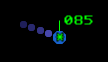
about them (e.g., the aircraft type, the planned route, etc.) Such radar tracks are rendered like this:
There is a position symbol (here, an asterisk), and a green leader line connecting the
position symbol to the datablock, which here just shows the radar track's altitude, in hundreds of feet.
The purple dots to the left are the history trail, showing the aircraft's position 5, 10, 15, ...
seconds in the past.
Some radar tracks have flight plans associated with them; such tracks are called associated tracks
(and tracks without a flight plan, as the one above, are unassociated.)
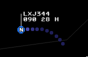
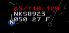
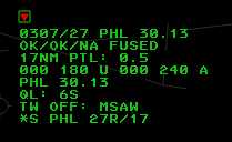
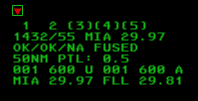
Given a flight plan, STARS is able to provide more useful information in the aircraft's datablock, as shown here:
Here we see the datablock showing the aircraft's callsign, LXJ137, its altitude in hundreds of feet (040)
multiplexing with its destination airport (CDW), and its groundspeed in tens of knots (28) multiplexing with
its aircraft type, CL30. The "H" after groundspeed is the aircraft's consolidated wake turbulence (CWT) category—upper small. (See the section on datablocks for extensive documentation of datablocks and the information that they may show.) For this aircraft, the "P" in the middle of the circle (the position symbol) indicates which controller is the owner of the aircraft's track. (In contrast, unassociated tracks cannot be owned by a controller.)
Most IFR aircraft automatically have flight plans associated with them.
For VFR aircraft or for VFRs that request pop-up IFR clearance, a variety of commands are available to
create flight plans and associate them with aircraft; see the section on Flight Plans below.
A single controller may own an aircraft's track and a single controller may own control of an aircraft. The same controller may own both or two different controllers may own each track and control. A controller must have control of an aircraft in order to issue instructions to the pilot. See the discussion of Track Ownership below for more information about how control and track ownership are transferred between controllers.
Each controller in the terminal environment is responsible for at least one terminal control position (TCP).
(A single controller may cover multiple positions when multiple positions have been consolidated.)
Each TCP is identified by three characters:
- The first character gives the facility; more or less the TRACON or ATCT/TRACON where the position is located.
- Facilities are split into multiple areas; the second character which area the TCP is in.
- Finally, each area is split into sectors; these are denoted by the third character.
Consider for example the N4P TCP: the N indicates the
N90 (New York) TRACON; the 4 is for the fourth area (which is the Newark area)
of N90; finally, the P is the Yardley sector of the Newark area.
Controllers interact with the STARS system via a terminal controller workstation (TCW), which
consists of a physical display and keyboard. Each TCW has an identifier that corresponds to a single TCP.
Normally a TCW is responsible for just that one TCP, but through consolidation,
a TCW may be responsible for multiple TCPs. (In many scenarios, a controller will be responsible for
multiple TCPs.)
Other controllers, both real and virtual, may be signed in when you're running a vice scenario.
The list of controllers is available in the "Controllers" drop-down in the scenario information window.
Among other useful information, it shows the TCP identifier associated with each controller
and whether the controller is human.
Entering Commands
Some STARS commands are entirely keyboard based: you enter a
command and hit the [ENTER] key to issue the command.
As you type, your input will be shown in the input area,
which is by default on the left side of the screen.
Entering a space starts a new line.
To edit your input, the backspace key can be used.
Alternatively, pressing [ESCAPE] clears the input and
any errors that are displayed.
Many STARS commands involve selecting an aircraft that they
apply to; in
STARS this is called "slewing" the aircraft. To slew an
aircraft in vice, click on its radar track with the
left mouse button. You will often enter a command with the
keyboard and then slew an aircraft; if the documentation
below, [SLEW] indicates that an aircraft should
be slewed to execute the command. In the following, if a listed command
doesn't end with [SLEW], then it should be understood
that [ENTER] must be pressed to execute the command.
Many STARS keyboard commands take additional parameters such as an aircraft
callsign, a beacon code number, or a controller identifier. The following
notation is used for these entries in the documentation below:
| Identifier |
Format and Use |
(##) |
Numeric digits: the number of hash marks "#" indicates the number of
expected digits. When used for beacon code values, only the digits 0-7 are valid. |
(ABC) |
Arbitrary letters: any three letters. |
(CID) |
Control position identifier: letters and digits identifying a control position,
either inside the local facility or external.
There are a number of rules that define how these are specified; they are
discussed in more detail below. |
(FLT ID) |
Flight identifier: either a full aircraft callsign, the beacon code
that an aircraft is squawking, or the tab list index for the aircraft. (Tab list
indices can be found as two digits in the first column of some STARS system lists
such as the VFR and FLIGHT PLAN lists as well as coordination lists. |
(TCP) |
TCP identifier: a numeric digit followed by a letter identifying a local terminal
control position. |
The STARS keyboard has a number of custom keys that are not present on standard keyboards.
In the following documentation, when one of the STARS keys in square brackets below is shown, the corresponding
regular keyboard key should be entered.
| STARS |
Regular |
[BRITE] | [Ctrl-F5] |
[CA] | [F11] |
[CHARSIZE] | [Ctrl-F7] |
[CNTR] | [Ctrl-F2] |
[DCB-SHIFT] | [Ctrl-F7] |
[DCB] | [Ctrl-F9] |
[F13] | [Shift-F1] |
[FLT DATA] | [F6] |
[HND OFF] | [F5] |
[INIT CNTL] | [F1] |
[LDR] | [Ctrl-F6] |
[MAPS] | [Ctrl-F3] |
[MIN] | [End] or \ |
[MULTIFUNC] | [F7] |
[PREF SET] | [Ctrl-F12] |
[RANGE] | [Ctrl-F11] |
[RNGRING] | [Ctrl-F10] |
[SHIFT] | [Ctrl-F8] |
[SITE] | [Ctrl-F14] |
[TERM CNTL] | [F4] |
[TGT GEN] | [Tab] |
[TRIANGLE] / ∆ | ` |
[TRK RPOS] | [F2] |
[TRK SUSP] | [F3] |
[VP] | [F9] |
[WX] | [Ctrl-F4] |
When issuing a command leads to an error, STARS prints an
abbreviated message above the input area. These are the error
codes that vice currently uses:
| Code |
Description |
| FORMAT |
Error in the format of the command; for example,
specifying a non-numeric value where a number was expected.
|
| DUP BCN |
Duplicate beacon code: the same squawk code has
been assigned to multiple aircraft. |
| DUP CMD |
Duplicate command: a command has been entered a second time and is no longer applicable. |
| ILL ACID |
Illegal aircraft id. |
| ILL ATIS |
Illegal ATIS code. |
| ILL AIRPORT |
Illegal airport: either the airport does not exist
or the command does not apply to it. |
| ILL CODE |
Illegal beacon code: an illegal squawk code was entered. |
| ILL FIX |
Illegal fix: the fix specified does not exist. |
| ILL FLIGHT |
Illegal flight: no flight plan is filed for the specified callsign. |
| ILL FNCT |
Illegal function: the command cannot be executed. |
| ILL LINE |
Illegal Tab line index entered: no aircraft is associated with that number. |
| ILL MAP |
Illegal map: an invalid map was specified to be
displayed or hidden. |
| ILL PARAM |
Illegal parameter: the command specified had an
invalid parameter. |
| ILL POS |
Illegal position: the control position specified
is invalid or does not exist. |
| ILL PREFSET |
Illegal preference set: the preference set specified
is invalid or does not exist. |
| ILL RPC |
Illegal runway pair configuration specified for CRDA. |
| ILL RWY |
Illegal runway. |
| ILL SCR |
Illegal scratchpad: the scratchpad specified for
an aircraft does not meet the requirements of a valid scratchpad. |
| ILL SECTOR |
Illegal sector: the controller specified is
invalid. |
| ILL TRK |
Illegal track: another controller owns the
aircraft's track, so the command is disallowed. |
| ILL VALUE |
Illegal value: the value specified is
illegal (e.g., an impossible altitude). |
| MULTIPLE FLIGHT |
Multiple flights apply. |
| NO FLIGHT |
No flight: there is no aircraft with the specified callsign. |
| RANGE LIMIT |
Invalid weather range specified. |
Specifying Controllers
A number of STARS commands take controller IDs to specify other controllers; examples include handoffs and
point outs. The following rules apply to them:
- For pairs controllers in the same facility, the full TCP may be entered,
or the facility may be omitted and only the area
and sector given. Thus, for a handoff from Yardley,
N4P, to
LaGuardia departure, N1L, the Yardley controller could specify 1L
for LaGaurdia departure.
- If the other controller is in the same area of the same facility, then only the sector needs to be entered: for example,
N4P
can hand off to N4A, the Newark North arrival position, just by specifying A for
the TCP.
- For TCPs outside of the facility, the delta (∆) symbol must be specified before the TCP; in
vice delta is mapped to the backtick key. The full three-letter TCP may be given,
though the area and sector may be omitted if the facility only has one TCP.
- To handoff to an enroute controller, the enroute facility identifier and sector must be provided;
enroute sectors are identified by two-digit numbers.
For the home ARTCC, the facility identifier is generally
C,
unless a neighboring ARTCC's facility identifier is "C", in which case
the facility identifier for the home ARTCC changes from a "C" to the regular facility identifier.
Thus, for ZNY, "N" is used rather than "C". The sector may be omitted
if there is only one enroute controller signed on.
- For handoffs, airspace awareness rules may be
provided in the scenario definition; these are rules that associate specific controllers with
departing aircraft based on their altitude, the fix they are flying to, and possibly their aircraft type.
When such a rule applies to an aircraft, a handoff to a corresponding enroute controller can
be initiated simply by entering the enroute facility identifier, without the sector.
For a handoff to a controller in a neighboring facility where an airspace awareness rule applies,
just ∆ and the facility id are sufficient.
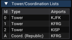
The airspace awareness definitions in a scenario can be found in the scenario information window,
accessed by clicking in the main menu bar.
The following STARS commands offer further control over how airspace awareness is applied:
| Command |
Function |
[HND OFF]CXE |
Enables airspace awareness for interfacility handoffs.
|
[HND OFF]CXI |
Disables ("inhibits") airspace awareness for interfacility handoffs.
|
[HND OFF]CTE |
Enables airspace awareness for intrafacility handoffs.
|
[HND OFF]CTI |
Disables ("inhibits") airspace awareness for intraacility handoffs.
|
[HND OFF]CE |
Enables airspace awareness for both inter- and intrafacility handoffs.
|
[HND OFF]CI |
Disables airspace awareness for both inter- and intrafacility handoffs.
|
The Cursor Home and Hiding the Cursor
After a keyboard command is entered, the STARS cursor may be optionally returned to a "home"
position and hidden. It will then reappear when the mouse is moved. The "CURSOR HOME" button in the
auxiliary DCB menu can be used to toggle this behavior.
If not specified using one of the following commands, the default home position is at the upper-left
of the SSA list.
| Command |
Function |
[MULTIFUNC]IHS |
Enables auto cursor home. |
[MULTIFUNC]INH |
Disables auto cursor home. |
[MULTIFUNC]INC[SLEW] |
Enables auto cursor home and sets the home position to be the slewed location on the radar scope. |
[MULTIFUNC]I* |
Clears the preview area and returns the cursor to the home position. |
Quick Reference
For basic controlling, a small number of STARS commands are used frequently.
The following table lists them and gives a short description of their operation.
| Command |
Description |
[SLEW] | Any of the following that apply (in order of precedence):
- Accepts the handoff of an aircraft's track from another controller (including redirected handoffs).
- Cancels an outbound handoff to another controller.
- Acknowledges a point-out from another controller.
- Recalls a point-out that you initiated.
- Clears the point-out color indication after a point-out has been acknowledged or rejected.
- Acknowledges an alert for an aircraft such as a collision alert (CA),
mode C intruder (MCI), minimum safe altitude warning (MSAW), or an alert due to the aircraft
squawking a special purpose code (e.g., 7600 for loss of radio).
- Removes a full datablock forced by a special condition.
- For a track in beacon mismatch, updates the assigned beacon code to match the squawked code.
- For a suspended track, displays the flight plan in the preview area.
- Inhibits the duplicate beacon code indicator.
- Clears blinking indicators (e.g., after a rejected handoff).
- Returns the datablock to unowned color after an outbound handoff is accepted.
- For an owned track, displays the beacon readout (ACID, squawked code, assigned code) in the preview area.
- Toggles between the full and partial datablock for an unowned track.
- Clears a forced quicklook from another controller.
- Inhibits the "no flight plan" alert for an unassociated track.
- For an unassociated track, temporarily displays the full limited datablock.
|
(CID)[SLEW] | Offers to handoff the
track of the aircraft to the controller identified by (CID). |
(scratchpad)[SLEW] | Sets
the scratchpad of the aircraft to (scratchpad). |
.[SLEW] | Clears the
aircraft's scratchpad. |
+(###)[SLEW] | Sets the
aircraft's assigned assigned altitude (which is shown in its datablock). |
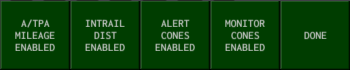
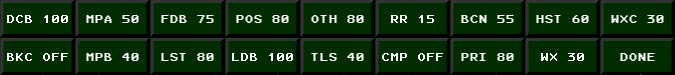
The DCB
The display control bar (DCB) is a menu that is shown by default at the top of the STARS window.
Many aspects of STARS's behavior can be configured using the DCB.
There are four types of buttons in the DCB:
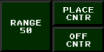
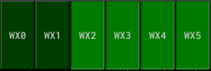
- Toggle buttons: these enable and disable various features. When enabled, they have a lighter
color than usual and appear depressed (like the "OFF CNTR" and "WX 3", "WX 4", and "WX 5" buttons above.) Clicking them
toggles whether they are enabled.
- Menu buttons: when clicked, they replace the contents of the DCB with those for another
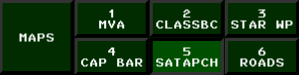
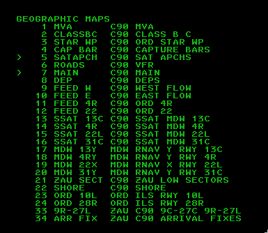
DCB menu. For example, clicking "MAPS" from the main DCB brings up a menu for configuring which
STARS video maps are displayed.
- Spinners: these allow setting various STARS parameters using the mouse wheel. For example, clicking "RANGE" allows setting the radar's range in nautical miles. Spinners capture the mouse and don't allow the cursor to leave their button until the user either clicks the mouse or presses the
[ESCAPE] key. When a spinner is active, it is also possible to enter a new value for it using the keyboard and then pressing [ENTER].
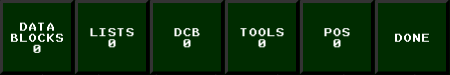
- Disabled buttons: these are shown in dark grey and represent STARS functionality that is not currently available in vice.
DCB submenus generally have buttons that return to the main DCB menu—look for a button labeled "DONE" or "SHIFT". Alternatively, pressing the [ESCAPE] key will return to the main DCB menu.
The main DCB menu offers the following controls:
Here is the auxiliary DCB:
Many of its buttons are disabled; the enabled ones are:
Press the [DCB] key (control-F9) to Toggle whether the DCB is visible.
Track Ownership
Controllers must both own an aircraft's track and have control of the aircraft in order to issue
instructions to the aircraft's pilot. Managing ownership of tracks
and control of an aircraft is at the core of how multiple controllers work together to
control an aircraft; it is crucial that controllers hand off both the track and control of an
aircraft before it enters another controller's airspace.
Untracked Aircraft
When an aircraft departs an airport, its track and control may not be owned by any controller.
VFR aircraft may also enter a controller's airspace without being tracked; these are known as
unassociated tracks since there is no flight plan associated with them.
These aircraft have a limited datablock, which only shows the aircraft's altitude in hundreds of feet.
The datablock is drawn in green indicating that the current controller does not own it,
and the asterisk shown in the position symbol at the center of its track (the blue dot) also indicates that its track is
unowned.
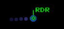
If an unassociated track's transponder is turned off, it appears with a plus sign
in its position symbol and no altitude is shown; such a track is also referred to as a primary-only or
primary track, since no secondary information is returned by its transponder.
If its transponder is on but it is not squawking altitude, a diamond is used for its position symbol.
Here are some examples.
Departures contact the appropriate controller on the radio once they're a few hundred feet off the ground;
look for a message in the input window below the STARS scope:
For departures, you may disable the "Auto track departures" checkbox
in the "Settings" window to not automatically initiate track on the departing aircraft that you are
responsible for in the current scenario.
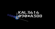
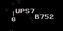
When you own an aircraft's track, the datablock becomes white a full datablock
and the letter corresponding to your position's TCP (here, "G") will appear at the center of the radar track.
Note that you can not issue control instructions to an aircraft unless it is on your radio
frequency. If you track a departure before it contacts you, it
is still under the tower's control and tuned to the tower's
radio frequency. Once the (virtual) tower controller tells the aircraft to "contact
departure", they will check in with a message on your radio frequency. It is at this point
that you also have control of the aircraft and can start
issuing control commands to it.
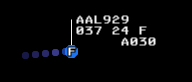
Inbound Handoffs
Aircraft entering your airspace will be generally owned by another controller (human or virtual) before they
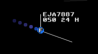
are handed off to you. Initially, they are displayed with a partial datablock
that shows altitude in hundreds of feet, groundspeed in tens of knots, and the
scratchpad, if set.
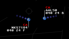
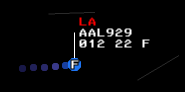
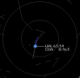
Often it is a center controller who owns the aircraft and a "C" will be displayed for the position id,
as in the example below:
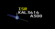
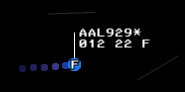
The controller who owns the aircraft's track may eventually hand it off to you;
at this point, the datablock will turn white, start flashing, and change to a full datablock as shown below.
The datablock will continue flashing until you accept the handoff by slewing the aircraft's
radar track using one of the following commands:
| Command |
Function |
[SLEW] |
Accepts the handoff of the slewed aircraft (if it is being handed off!).
|
[HND OFF] |
Accepts the aircraft being handed off that is closest to the center of the range rings.
|
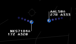
After a handoff is accepted, the aircraft's datablock will stop flashing and remain white.
However, as with departures, you do not have control of the aircraft until the other controller
instructs the aircraft to contact you, transferring control as well.
After the aircraft contacts you on the radio, you may start issuing control instructions to it.
Outbound Handoffs
When you are ready to hand off an aircraft's track to
another controller, a number of commands are available to do so:
| Command |
Function |
(CID)[SLEW] /
[HND OFF](CID)[SLEW] /
[HND OFF](CID) (FLT ID) |
Initiates a handoff of the slewed aircraft to the specified controller.
|
[SLEW]/
[HND OFF][SLEW] /
[HND OFF](FLT ID) |
Cancels an initiated handoff to another controller.
|
(For these commands, determining the correct controller ID to enter has a few
subtleties and is discussed further below.)
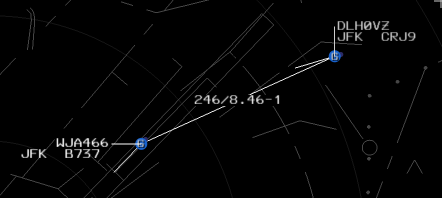
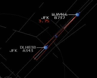
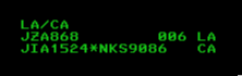
The datablocks of outbound handoffs have an identifier for the target controller stuffed into
the second line of the datablock, four characters in. For JBU52 below, it is "V", corresponding
to the intrafacility position "1V" that the aircraft is being handed off to, and for TAM9021,
it is "C", corresponding to a center position. For handoffs outside the facility (including to center),
the position identifier is shown in the datablock multiplexed with the altitude and scratchpad (it is "N86" for TAM9021.)
After the other controller accepts the handoff, control of the aircraft's track is
transferred to them. The aircraft's datablock will start
flashing to notify you of this and the letter on the track will switch to be the
other controller's. After a few seconds the datablock will stop flashing.
Note that at this point you still retain control
of the aircraft and can issue control instructions to it since you haven't yet transferred control to
the other controller.
When you are ready to transfer control of the aircraft to the controller who has
accepted the track, enter the FC command in the command input window and slew the aircraft.
This will instruct the aircraft to switch frequencies to the next controller.
Clicking on the track of an aircraft that has been handed off causes the datablock
color to switch to green; this can be used to remember that you have transferred
communications of an aircraft to the other controller.
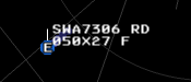
Redirecting Handoffs
An incoming handoff can be redirected to another TCP by entering the TCP's ID and slewing the aircraft, just as if
you owned the track and were handing it off. Doing so will add RD to the datablock shown to the handoff initiator
and the redirector, and show the TCP to where the track was redirected to. This also turns the datablock green for the redirector.
Here is a datablock for a redirected handoff as seen by the original handoff initiator; we can see that it has been
handed off to the "X" TCP at the facility.
Redirected handoffs can be canceled using the same commands as are used for canceling regular handoffs.
Terminating Control
In addition to handing off tracks to other controllers; a controller may terminate control, otherwise known as
"radar services terminated, frequency change approved".
The following commands are available:
| Command |
Function |
[TERM CNTL][SLEW] /
[TERM CNTL](FLT ID) |
Drops the track of the specified aircraft.
|
[TERM CNTL]ALL |
Drops the tracks of all aircraft under the controller's control.
|
Point Outs
Point outs let controllers direct another controller's attention to an aircraft; some facilities may have prearranged
coordination procedures where an aircraft may pass through another controller's aircraft after a point out, or a point out
may be performed before verbally coordinating with another controller. The following commands are available for point outs:
| Command |
Function |
(CID)*[SLEW] |
Points out the slewed aircraft to the specified controller.
|
[SLEW] |
Cancels a point out of an aircraft.
|
UN[SLEW] |
If the aircraft is being pointed out to the controller, rejects the point out.
|
[HND OFF][SLEW] |
If the aircraft is being pointed out to a controller, takes ownership of the aircraft's
track. |
[MULTIFUNC]O[SLEW] /
[MULTIFUNC]O (FLT ID) |
Prints the point out history—up to the last 20 TCPs to which the aircraft has been pointed out. |
[MULTIFUNC]O*[SLEW] /
[MULTIFUNC]O* (FLT ID) |
Clears the point out history for the specified track. |
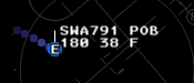
An outbound point out is shown on the originator's scope with "PO" to the right of the aircraft id,
followed by one character identifying the other controller's TCP. (Here, "B", for TCP 1B.)
An inbound point out causes the corresponding aircraft's datablock to switch to a FDB and flash yellow,
with "PO" shown after the aircraft id.
Clicking on a point out acknowledges it. This causes the datablock to stop flashing but leaves the datablock yellow.
A second click reverts to a green datablock, but leaves it as a FDB.
A third click will then change back to a regular green PDB.
On the originator's scope, an accepted point out causes a flashing "PO" to appear to the right of the aircraft id for a few seconds.
An inbound point out can be rejected by entering UN[SLEW]; a flashing "UN" is shown to the right of the datablock
on the originator's scope in this case.
Position Consolidation
It is possible to change which human controller is responsible for which terminal control positions (TCPs)
while a simulation is running—more specifically, which TCPs a terminal control workstation (TCW)
is responsible for. One way this happens is when a new controller connects to a sim at an unoccupied TCW.
Another way is through explicit STARS consolidation commands,
which allow one TCW (the receiver) takes over the responsibilities
of another position (the sender).
Consolidation operates at the level of terminal controller workstations (TCWs). Each TCW may have a primary TCP
(the one that matches its identifier) and may have zero or more secondary TCPs that have been consolidated into it.
(Instructors and RPOs may sit at a TCW with no TCPs assigned to it.)
The controller at a TCW can control aircraft assigned to any the TCPs it owns, whether primary or secondary.
There are two types of consolidation:
- Basic: The receiving TCW takes control of inactive and future flights from the sender.
Inactive flights are flight plans that are not yet associated with a radar track. Future flights are those
that have not yet departed or entered the airspace.
- Full: The receiver takes control of all flights from the sender, including
active flights that are currently being controlled.
The following commands are available for consolidation. In these commands, the triangle character (∆)
can be entered to specify the current controller's TCW as the receiver. TCPs and TCWs are specified as 1 or 2 characters;
if only 1 character (the sector) is given, the current controller's facility (controller subset) is assumed
(e.g., a controller at 2G may specify 2K as either "K" or "2K", but must specify 3H as "3H".)
| Command |
Function |
[MULTIFUNC]C∆(TCP) |
Basic consolidation: consolidates inactive and future flights from the specified sender TCP to the current controller's TCW.
Active flights remain at the sender's keyboard until handed off or coasted out. |
[MULTIFUNC]C(TCW)(TCP) |
Basic consolidation: consolidates inactive and future flights from the specified sender TCP to the specified receiver TCW. |
[MULTIFUNC]C∆(TCP)+ |
Full consolidation: consolidates all flights (active, inactive, and future) from the specified sender TCP to the controller's TCW. |
[MULTIFUNC]C(TCW)(TCP)+ |
Full consolidation: consolidates all flights from the specified sender TCP to the specified receiver TCW. |
[MULTIFUNC]C |
Deconsolidates the current controller's primary TCP, returning it to its default keyboard. |
[MULTIFUNC]C(TCP) |
Deconsolidates the specified secondary TCP, returning it to its default keyboard. |
[MULTIFUNC]D+ |
Displays the current consolidation status in the Preview area. Shows which positions are consolidated
and under which primary position. Basic consolidations are indicated with an asterisk (*) prefix. |
When positions are consolidated, the receiver's TCW gains responsibility for aircraft assigned to the sender TCP.
The receiver controller sees and controls these aircraft alongside those assigned to their primary TCP.
Note that aircraft tracks remain assigned to their original TCP; if the sender TCP is later deconsolidated
(returned to its own TCW), those tracks will be controlled by whoever is at the sender's TCW.
Track Information
Much information is encoded in the radar track symbol of an aircraft and the
datablock displayed next to it. STARS provides many different ways to configure
how this information is presented in an effort to balance providing the necessary
information about aircraft that are important to a controller while minimizing the
visual clutter from aircraft that are less relevant.
Track Symbols
The location of each aircraft visible to RADAR is shown using a primary target symbol.
Which shape is used for the symbol depends on which RADAR mode has been selected and which
RADAR sites are active.
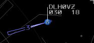
FUSED is the default radar mode, in which case a small blue circle is used for aircraft tracks, as in the examples so far.
In MULTI mode, a small blue rectangle is used in place of the circle and the rectangle is oriented
based on the aircraft's heading; this example is flying in a northeasterly direction:
In SINGLE mode, a blue rectangle is also used, but the size of the rectangle
varies based on how close the track is to the RADAR site and the rectangle is
oriented toward the RADAR site rather than according to the aircraft's heading.
The track is bigger the farther
away it is from the RADAR site, which helps show the degree of uncertainty in its position.
SINGLE mode also includes a green line on the far side of the track with respect
to the RADAR site's position. This track is 50 miles from the RADAR site so has a relatively
large rectangle, and the RADAR site is to the East, so the green line is on the left:
In SINGLE mode, if the aircraft is very far from the RADAR site, only the outline of the blue
rectangle is shown.
The brightness of track symbols is controlled using "PRI" in the DCB BRITE menu.
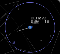
Track History
STARS can draw a trail of small purple circles behind a track to show its prior path.
The number of circles drawn and the time between adding a new circle to the trail is set
using the HISTORY and H_RATE buttons in the auxiliary DCB:
HISTORY sets the number of history dots; it may range from 0 to 10.
Here is a track with a full complement of 10 history dots:
H_RATE sets the time in seconds before STARS tries to add another history dot.
Note that after this time passes, STARS does not immediately add another dot; rather, it waits
until the next RADAR position is received for the aircraft. Under FUSED RADAR mode, positions
are received every second, and under MULTI and SINGLE modes they are received every 5 seconds.
Thus, for example, under FUSED mode with a H_RATE of 4.5, a new history dot is added every 5 seconds:
STARS waits 4.5 seconds since adding the previous dot, which by definition occurred when a new
RADAR position was received. When the next arrives in 0.5 more seconds, a dot is added, leading
to a 5 second overall rate.
The brightness of track symbols is controlled with "HST" in the DCB BRITE menu.
Position Symbols
All tracks have a single-character position symbol at
their center that indicates which controller owns the track.
Position symbols are determined as follows:
- If the track is owned by a controller in the current controller's facility, the
controller's sector ID is used. (For example, if
N4P is the current
controller's TCP, an aircraft controlled by N1V would be shown with an "V".
- If the track is owned by a terminal controller in an adjacent facility, the facility
id is shown.
- If the track is owned by an enroute controller, either "C" or the enroute facility ID is shown.
The brightness of track symbols is controlled using "POS" in the DCB BRITE menu.
For unassociated primary tracks that are not squawking altitude, the triangle that is
normally drawn for their position symbol can be disabled.
| Command |
Function |
[MULTIFUNC]2PI |
Inhibits the display of the position symbol for unassociated primary tracks. |
[MULTIFUNC]2PE |
Enables the display of the position symbol for unassociated primary tracks. |
For unassociated tracks that do have functioning transponders, is also possible to select
individual beacon codes or beacon codes blocks; unassociated aircraft squawking matching beacon codes
are then displayed with different position symbols than the usual.
By default, all 12xx beacon codes are handled this way.
In that case, aircraft not squawking altitude are drawn with a triangle position symbol and those that
are are drawn with a square.
| Command |
Function |
[MULTIFUNC]B(##) /
[MULTIFUNC]B(####) |
Toggle the display of either a single beacon code (if four digits are entered)
or a beacon code bank (if two digits are entered). Beacon code banks are identified
by the first two digits; for example B12 toggles the 12xx beacon code block.
|
[MULTIFUNC]B* |
Clear all selected beacon code blocks.
|
Datablock Types
There are three datablock formats that may be used, depending on circumstances: limited datablocks (LDBs),
partial datablocks (PDBs), and full datablocks (FDBs)s.
Limited Datablocks (LDBs)
Limited datablocks are shown when a target is not tracked by a TCP.
By default, they only display the altitude's altitude in hundreds of feet, though if the track
is slewed, they display the aircraft's assigned squawk code and groundspeed for a short period of time.
A few commands are also available to control the display of squawk (beacon) codes in LDBs:
| Command |
Function |
[MULTIFUNC]B |
Toggle the display of beacon codes in LDBs. |
[MULTIFUNC]B(SLEW) |
Toggle the display of the beacon code for an unassociated aircraft. |
[MULTIFUNC]BE(SLEW) |
Enable the display of the beacon code for an unassociated aircraft. |
[MULTIFUNC]BI(SLEW) |
Disable the display of the beacon code for an unassociated aircraft. |
The brightness of LDBs is controlled using LDB in the DCB BRITE menu.
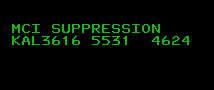
If a departing aircraft is squawking a non-1200 code but there is no flight plan for the
code they are squawking, a flashing "WHO" is displayed in their LDB next to the code they are squawking:
Clicking on the track clears the "WHO".
If you're searching for an unassociated aircraft squawking a specific beacon code, the beacon code display command
can be used to cause all aircraft squawking that code to flash it in yellow in their limited
datablock.
| Command |
Function |
**#### |
For all unassociated aircraft squawking the entered beacon code, display the beacon code
in flashing yellow text in their limited data block for a short period of time.
|
Partial Datablock (PDBs)
Partial Datablocks are associated datablocks that are owned by another controller.
They show the aircraft's altitude and groundspeed (in tens of knots), followed by a letter indicating
its consolidated wake turbulence (CWT) category; see below for more information about CWT.
The altitude may alternate with the aircraft's scratchpad or destination airport, as in the example below:
Some STARS facilities use variations on the above PDB format: they may also include the secondary
scratchpad, time-share the aircraft type with the groundspeed and CWT category, not include the groundspeed,
or show the groundspeed and CWT category separately.
Slewing a PDB converts it to a full datablock; a second slew returns it to a PDB.
The brightness of PDBs is also controlled using LDB in the DCB BRITE menu.
Full Datablock (FDBs)
Full datablocks provide the most information about aircraft; at minimum, they show the aircraft identifier
(i.e., its callsign), its altitude in hundreds of feet, its groundspeed in tens of knots, a letter denoting
its CWT category, and the aircraft type. Groundspeed and CWT category alternate with the aircraft type, as shown here:
Various other information may be present in a FDB. Here we see the primary scratchpad "L30" and the secondary
scratchpad "DEP" alternating with the altitude, where a "+" after "DEP" indicates that the secondary scratchpad
is shown. We also see a temporary controller-assigned altitude of 12,000 feet indicated by "A120" in the third line.
The brightness of FDBs is also controlled using FDB in the DCB BRITE menu.
The FDB is displayed for a track if any of the following is true:
- The track is owned by the current controller.
- The track is being handed off from another controller to the current controller.
- The track is a redirected handoff where the current controller has either redirected it or had it redirected to them.
- Another controller has pointed out the track to the current controller and the point out hasn't been cleared.
- The user has clicked on a track owned by another controller.
- The track is owned by a controller whose sector id the user has quicklooked.
- The track has been force quicklooked to the current controller by another controller.
- "Quick look all" has been enabled by the controller.
- The aircraft is squawking a special purpose code (e.g., 7700 for an emergency) or if it has an active safety alert (e.g., low altitude).
- The aircraft's beacon code matches one being displayed via the
**#### command.
- The "overflight full datablocks" option is enabled and the track is an overflight.
Other than the commands related to modifying Flight Plans that can lead to changes
in what entries are shown in the FDB, there is just one command to manage the FDB's contents:
| Command |
Function |
[FLT DATA][SLEW] |
Toggles display of the aircraft type in the FDB. |
A few commands are also available to control whether the FDB is displayed for overflights that are not under the
user's control:
| Command |
Function |
[MULTIFUNC]E |
Toggle the display of the FDB for overflights. |
[MULTIFUNC]EE |
Enable the display of the FDB for overflights. |
[MULTIFUNC]EI |
Disable ("inhibit") the display of the FDB for overflights. |
"Beaconator"
The "beaconator" feature is enabled by holding the Control and F1 keys on the keyboard. In full datablocks,
it causes the aircraft id to be replaced with the code the aircraft is squawking. Partial datablocks show the sqwawk
code in the first line, and limited datablocks show the squawk code and aircraft id. Here is an example of all
three types of datablock, alternating with the beaconator enabled and disabled.
Datablock Control Commands
| Command |
Function |
[MULTIFUNC]E |
Toggle FDB for overflights
|
Additional Datablock Entries
A number of additional useful pieces of information can be found in datablocks, depending on the circumstances.
(See also the section on STARS Flight Plans for information
about a number of things such as scratchpads and altitude assignments that appear in datablocks
and are managed along with the aircraft's STARS flight plan.)
Ident
If a controller has instructed an aircraft to ident, a flashing "ID" will appear in its datablock.
In FDBs, "ID" replaces the CWT category next to the airspeed and the aircraft type is temporarily
no longer displayed. LDBs display the aircraft's squawk code and "ID" for identing aircraft,
and PDBs display "ID" at the end of the second line of the datablock.
Squawk Codes
If an aircraft is not squawking the beacon code assigned to it, the bottom line of the full datablock
shows both the code it is squawking (on the left) and the code it has been assigned (on the right).
The code that it should be squawking flashes to alert the controller.
Slewing the aircraft makes its assigned squawk code the same as the code it is currently squawking.
Consolidated Wake Turbulence (CWT)
Each type of aircraft has been assigned
a Consolidated
Wake Turbulence (CWT) category by the FAA. CWT categories range from "A" to "I" and go
in decreasing order of aircraft size. Aircraft CWT categories are shown in both PDBs and FDBs.
This table lists the categories and has representative
aircraft types for each one.
| Letter |
Category |
Examples |
| A |
Super |
A380 |
| B |
Upper Heavy |
A33*, A34*, A35*, B744, B77*, B788, B789 |
| C |
Lower Heavy |
A30*, A310, B76*, DC10, MD11 |
| D |
Non-Pairwise Heavy |
B74[1,3,D,R,S], B78X |
| E |
B757 |
B752, B753 |
| F |
Upper Large |
A31*, A32*, B73*, DH8D, E190 |
| G |
Lower Large |
CRJ*, GLF[2,3,4] |
| H |
Upper Small |
BE40, B350, C560, LJ* |
| I |
Lower Small |
BE20, C25[A, B], PA31, SR22 |
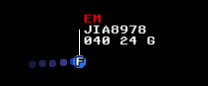
Special Purpose Codes (SPCs)
If an aircraft squawks a special purpose code (SPC) (e.g., 7600 for a radio failure, 7700 for an
emergency, etc.), the corresponding two-letter code is shown in red at the top of the FDB and an alert sounds.
The alert can be silenced by slewing the aircraft.
Here is an example for an aircraft squawking 7700.
The controller may also associate an SPC with an aircraft regardless of what it is squawking by entering a
SPC and slewing the aircraft. An alert sound is not played in this case. The following codes may be used:
| Command |
Function |
LL[SLEW] |
Associates the "lost link" SPC with the selected aircraft. |
HJ[SLEW] |
Associates the "hijack" SPC with the selected aircraft. |
RF[SLEW] |
Associates the "radio failure" SPC with the selected aircraft. |
EM[SLEW] |
Associates the "emergency" SPC with the selected aircraft. |
MI[SLEW] |
Associates the "military intercept" SPC with the selected aircraft. |
It is also possible to add custom codes for a facility via "custom_spcs" in "stars_config".
Custom SPCs are shown in yellow.
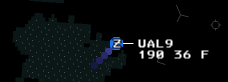
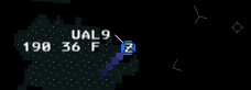
Leader Lines and Positioning Datablocks
Leader lines connect radar tracks to the datablocks of the associated aircraft.
They may have eight orientations, corresponding to the eight cardinal and ordinal directions.
Here is an example of a radar track with a leader line East of the aircraft (left) and
Northwest of it (right):
The DCB offers two buttons for configuring leader lines:
The top button, LDR DIR, is a spinner that controls the default direction of leader lines for
aircraft whose tracks that are owned by the current controller.
The bottom button, LDR, controls the length of all leader lines. The leader line length can
range from 0 to 7, with the range of lengths shown below:
A number of keyboard commands are available to specify leader lines, including ways to specify
them for subsets of the aircraft. These all use the numbers 1-9 to specify a
leader line direction; depending on the command, 5 may be used to clear a previously-set direction or
it may be invalid.
If you have a numeric keypad on your keyboard, you have an easy reference to
the association between numbers and directions; consider the aircraft to be at the position of
the "5" key and then the other numbers specify the direction of the leader line relative to the
aircraft. If you don't have a numeric keypad, visualize one, or refer to this figure:
A number of commands are available to configure leader lines, where all uses of (#)
below correspond to a number following the above convention for specifying directions:
| Command |
Function |
(#)[SLEW]/
[MULTIFUNC]L(#)[SLEW]/
[MULTIFUNC]L(#) (FLT ID) |
Sets the leader line direction for the aircraft, where (#) is a valid leader line direction specifier. 5 may be given to clear a previously-assigned direction. |
[MULTIFUNC]L(#)U |
Sets the default leader line direction for aircraft with unassociated tracks. |
[MULTIFUNC]L(#)* |
Sets the default leader line direction for aircraft tracked by other controllers. 5 may be given to clear a previously-assigned direction. |
[MULTIFUNC]L(TCP)(#) |
Sets the leader line for aircraft controlled by the specified TCP. If a one-letter TCP is entered for a controller in the same area, a space should be entered after it. 5 may be entered to clear a previously-assigned direction |
[MULTIFUNC]L(##)[SLEW]/
[MULTIFUNC]L(##) (FLT ID) |
Sets the default leader line for a single track system-wide, across all controllers' displays. 55 may be entered to clear a previously-specified direction. |
[LDR] |
Activates the LDR spinner in the DCB. |
Quicklook
"Quicklook" makes it possible to specify that all tracks owned by another controller will be shown with a full datablock
instead of a partial datablock. This can be useful when one controller is feeding aircraft to another; quicklook gives
some more visibility into the flow of inbound aircraft. When "quicklook plus" is used, the datablocks of quicklooked aircraft
are also shown in white rather than green. Facility engineers may also specify regions of airspace where quicklook
automatically applies.
A number of commands are available to control quicklook:
| Command |
Function |
(TCP)/
[MULTIFUNC]Q(TCP) |
Toggles quicklook for the specified control position. Multiple positions may be specified, separated by spaces.
If a "+" is included after the control position, quicklook plus is toggled.
If the user's current TCP is entered, the currently-quicklooked positions and enabled/disabled regions
are shown in the preview area—here is an example:
|
ALL/
[MULTIFUNC]QALL |
Enables "quicklook all", where all aircraft are shown as being quicklooked. |
ALL+/
[MULTIFUNC]QALL+ |
Enables quicklook all plus for all aircraft. |
[MULTIFUNC]Q |
Disables all active control position quicklooks. |
[MULTIFUNC]Q(region) E |
Enable the named quicklook region. |
[MULTIFUNC]Q(region) I |
Disable (inhibit) the named quicklook region. |
[MULTIFUNC]Q(region) |
Toggle whether the named quicklook region is enabled. |
[MULTIFUNC]Q* |
Disables all quicklook regions. |
The currently-active quicklook positions can be shown in the SSA list, after "QL:".
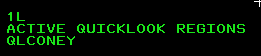
To see which if any quicklook regions are available, select the "MAPS" menu from the DCB
and then select "SYS PROC" to see the Processing Areas maps list. Quicklook regions can
then be found among those maps; here we see that "QLRGNS" represents all quicklook regions
and "QLCONEY" is an individual region:
Force Quicklook
A controller can also "force quicklook" a track that they own to cause its full datablock to be
shown on another controller's display. Force quicklooked aircraft also have yellow datablocks for the recipient,
until they clear the forced quicklook by slewing the track.
| Command |
Function |
**(TCP)[SLEW] |
Force quicklook the slewed track to the identified controller. Multiple controller IDs may be specified,
separated by spaces. "ALL" forces quicklook to all controllers.
|
**[SLEW] |
Force quicklooks the slewed track to the current controller (if enabled in the facility adaptation).
|
Dwell Mode
Dwell mode increases the brightness of the track and datablock of the aircraft closest to the mouse cursor,
if the mouse is reasonably close to a radar track. Here is an example of it:
It can be configured using the DWELL button in the auxiliary DCB; it may take the value OFF, ON, or LOCK.
OFF disables DWELL mode and ON enables it, with the increase in brightness lasting as long as the mouse cursor
is close to a track. With LOCK mode, the increased brightness of a track persists, even after the mouse cursor
moves away. Only when another track is approached by the mouse cursor does the brightness increase switch to it.
Dwell mode can also be configured using the keyboard:
| Command |
Function |
[MULTIFUNC]DE |
Enable the ON dwell mode.
|
[MULTIFUNC]DI |
Disable dwell mode.
|
[MULTIFUNC]DL |
Enable the LOCK dwell mode.
|
Altitude Filters
Controllers can set altitude filters to hide the datablocks and leader lines of aircraft outside a range of altitudes
of interest; doing so can help reduce the amount of clutter on the screen.
Here is an example of a track that is outside the filter range:
Note that if an track is pointed out or is an inbound handoff, its full datablock will still be shown, even if it is outside
of the current altitude filter.
STARS supports two filters, one for unassociated tracks and one for associated tracks.
Each of these filters is a range of altitudes, specified in hundreds of feet.
The following commands are available to manage altitude filters:
| Command |
Function |
[MULTIFUNC]F |
Display the current altitude filters in the preview area. The first filter range applies to unassociated
tracks and the second applies to associated tracks.
|
[MULTIFUNC]FC(###)(###) |
Specifies the altitude filter range for associated tracks.
The first three digits give the bottom altitude of the filter range and the second three digits
give the top of the filter range. Both altitudes are given in hundreds of feet.
|
[MULTIFUNC]F(###)(###) (###)(###) |
Specifies the altitude filter range for both unassociated and associated tracks.
The first three digits give the bottom of the filter range for unassociated tracks and the next
three give the top of the range for unassociated tracks, both in hundreds of feet.
The following pair of three digit numbers similarly give the filter range for associated tracks.
|
Flight Plans
vice offers a wide range of commands for creating flight plans on the fly for aircraft that didn't initially
file one; the main example of this currently is VFR aircraft that call asking for flight following.
A wide variety of are commands available to create flight plans in STARS—these are all documented in the
following. In practice, however, it's just necessary to understand two main flows, depending on which type
of flight plan is to be created:
- Local Flight Plans: these are intended for flights conducted wholly within delegated airspace of the current TRACON.
These flight plans are not sent to the host (overlying) ARTCC computer to be processed and forwarded
"downstream" to adjacent facilities. Examples include IFR/VFR pop up requests where the flight will not exit
the delegated airspace of the TRACON. However, local flight plans are not eligible for automated hand off to ARTCC.
If an adjacent TRACON is adapted to accept local flight plans, then they may be transferred via automated handoff.
- NAS Flight Plans: these are for aircraft that will enter adjacent facility airspace, for example, VFR aircraft
requesting radar advisories/flight following from a point within delegated TRACON airspace to a location outside of it.
STARS users are only permitted to create VFR NAS flight plans; IFR NAS flight plans would be entered via FDIO,
which is a separate system from STARS and not yet simulated/not needed for vice (for now).
VFR aircraft on NAS flight plans are eligible for automated handoff to adjacent facilities.
The most common way to enter a local flight plan is to type the aircraft's callsign, a space, the type of aircraft,
and press [Enter]. For example: N123AB C172. (Additional fields may be entered; see the
documentation below.) A summary of the flight plan will be printed in the preview area and the flight will appear
in the tab list ("FLIGHT PLAN"). The beacon code assigned to the aircraft can be found in either place.
The usual way to create a NAS flight plan is to enter the callsign, the entry and exit fix separated by an asterisk,
the aircraft type, and the requested altitude in hundreds of feet. Example: N123AB FRG*POU C172 085.
The entry fix is usually the departure point of the aircraft or a point (VOR) near where they call for flight following
and the exit fix is usually the VFR's destination; both must be three characters.
When STARS sends the a VFR NAS flight plan to the ARTCC computer and it is accepted, "VFR" is displayed to the right
of the aircraft's callsign in the "VFR LIST". The beacon code is displayed when received from ARTCC computer a few
seconds later. The flight also appears in the "FLIGHT PLAN" list.
For the full documentation of the flight-plan related commands below, in addition to the command components defined
above in Entering Commands,
a few additional parameters are commonly-found in commands related to flight plans.
Here are their definitions and syntax:
| Field |
Description |
(ACID) |
Aircraft identifier: an aircraft callsign starting with a letter and then
followed by letters or digits, no more than 7 characters long. Example: UAL650. |
(AC TYPE/EQ) |
Aircraft type: aircraft type optionally followed by a slash and a single character equipment suffix.
Example: C172/G.
|
(#/AC TYPE/EQ) |
Aircraft type: aircraft type optionally preceded by a number and a slash and
optionally followed by a slash and a single character equipment suffix; if specified,
the number gives the number of aircraft flying in formation.
Examples: 2/F16/G, B738.
|
(ASSIGNED ALT) |
Assigned altitude: three digits giving the aircraft's assigned altitude. An entry of 000
clears the assigned altitude.
|
(BEACON) |
Beacon code assignment: either four digits specifying a specific beacon code (####),
+ to specify a system-generated IFR code, / for a system generated VFR code,
or /1, /2, /3, or /4 to signify a code from the
associated beacon code bank.
|
(COORD TIME) |
Coordination time: 4 digits giving a time in Zulu for the flight's expected coordination time,
optionally followed by an "E". |
(FIX PAIR) |
VFR Fix Pair: three character entry fix followed by * and then a three character exit fix.
Optionally, a second * and the type of flight may follow.
Example: ISP*MVY. |
(FLIGHT TYPE) |
Type of flight: A for arrival, P for departure, or E for an overflight |
(PILOT ALT) |
Pilot-reported altitude: three digits giving a pilot-reported altitude in hundreds of feet.
000 clears the pilot-reported altitude. |
(REQ ALT) |
Requested altitude: three digits giving the requested (final) altitude for the flight. |
(RULES) |
Flight rules: a period followed by zero or one additional characters: V for VFR, P for VFR on top,
E for enroute (IFR), and no entry for none (IFR). Example: .V |
(SP1) |
Scratchpad 1: three (or up to four, at some facilities) characters for the aircraft's primary scratchpad entry. |
(SP2) |
Scratchpad 2: three (or up to four, at some facilities) characters for the aircraft's secondary scratchpad entry. |
(TCP OR FIX PAIR) |
TCP/Fix pair: either a number and a letter corresponding to (TCP) or a (FIX PAIR). |
Creating Flight Plans
STARS offers numerous commands for controllers to enter new flight plans; most start with
one or more required fields that are then followed by optional fields. Spaces separate all
fields, both required and optional. See the table above of common
components of flight plans for the rules for the format of the following entries.
The following create new flight plans that are not yet associated with an aircraft;
these flight plans are shown in the FLIGHT PLAN system list and/or the VFR LIST,
depending on their type.
| Command |
Function |
(ACID) (FIX PAIR) (AC TYPE/EQ) |
Create a NAS VFR flight plan with
an automatically-assigned squawk code. Optional additional fields: (REQ ALT) and
(TCP). The flight plan is assigned
to the controller who created it if no other controller is specified via (TCP).
Example: N123AB FRG*HPN C172/G 045. |
(ACID) |
Create a local flight plan.
Optional additional fields: (BEACON), (FLIGHT TYPE),
∆(SP1), +(SP2), (#/AC TYPE/EQ), (REQ ALT),
and (RULES).
Example: N123AB 6502 ∆ARR +R22 280. |
[INIT CTRL](ACID) (BEACON) |
Create a flight plan with a specified beacon code.
Optional additional fields: ∆(SP1) +(SP2) (#/AC TYPE/EQ). |
[VP](ACID) (VFR FIX PAIR) (AC TYPE/EQ) |
Create a VFR flight plan.
Optional additional fields: (REQ ALT) and (TCP). |
[FLT DATA](ACID)[ENTER] |
Create a new flight plan.
Optional additional fields: (BEACON), (TCP OR FIX PAIR),
(COORD TIME), ∆(SP1), +(SP2),
(#/AC TYPE/EQ), (REQ ALT), and (RULES). |
*(####) |
Create a "quick flight plan" with the specified beacon code.
The flight plan's ACID is automatically set with a predefined prefix that is followed
by the given beacon code. A flight rules suffix may optionally be given immediately after
the beacon code: E for enroute IFR, V for VFR, or P for VFR on top.
If no suffix is given, a local non-enroute IFR flight plan is created. |
It is also possible to create a new flight plan and immediately associate it with a track.
For both of the following commands, if the beacon code isn't specified, the code that the track
is currently squawking is used as the assigned code.
| Command |
Function |
(ACID)[SLEW] |
Create a new flight plan and associate it with the slewed track. Optional additional parameters:
(BEACON), ∆(SP1), +(SP2),
(ASSIGNED ALT), and (#/AC TYPE/EQ). |
[INIT CTRL](ACID)[SLEW] |
Create a new flight plan and associate it with the track.
Optional additional parameters:(BEACON), ∆(SP1), +(SP2),
(ASSIGNED ALT), and (#/AC TYPE/EQ). |
Y[SLEW] |
Creates a "quick ACID flight plan" with an automatically generated callsign and associates it
with the slewed track. The track's datablock is drawn in yellow until the track is slewed
a second time. |
Activating Existing Flight Plans
If an unassociated track is squawking the beacon code associated with a flight plan, the flight plan
will often automatically associate with the track. (This may not happen if the aircraft is outside
of the predefined regions in a TRACON where flight plans automatically associate, but it is generally
the case.) Alternatively, a command is available to associate an existing flight plan with a radar track.
| Command |
Function |
[INIT CTRL](FLT ID)[SLEW] |
Activate the identified flight plan and associate it with the slewed track.
Takes the following optional parameters to modify the flight plan before it
is associated: (SP1), ∆(SP1), (+SP2),
and (ASSIGNED ALT). |
Deleting Flight Plans
Two commands are available for deleting flight plans. If a flight plan is associated with a
track, the track becomes unassociated if it is deleted.
| Command |
Function |
[TERM CNTL](FLT ID) |
Deletes the flight plan identified by the flight identifier. |
[VP](FLT ID) |
Deletes the VFR flight plan identified by the flight identifier. |
[TERM CNTL]ALL |
Deletes all flight plans controlled by the controller. |
Flight Plan / Beacon Code Display
After a flight plan is created (and in some cases, after it is modified), an abbreviated version
of the flight plan is displayed in the preview area. Here is an example:
We have an aircraft with callsign ANA203 that has aircraft type A388. The "/A" is its CWT weight class—super.
It has been assigned beacon code 1711 and controller 2G is responsible for it.
It is departing JFK airport and its exit fix is GAYEL, shortened here to "GAY".
Its expected departure time is 2230 zulu, and its requested altitude is 37,000'.
There are also commands to cause a selected flight plan to be displayed:
| Command |
Function |
[MULTIFUNC]D[SLEW] /
[MULTIFUNC]D(FLT ID) |
Display flight plan
|
[MULTIFUNC]B[SLEW] |
If the slewed aircraft is associated, display its aircraft id, received, and assigned
beacon code in the preview area.
|
Modifying Flight Plans
For the following commands, if (FLT ID) is used to specify the flight plan,
the command can be used both for associated and unassociated flight plans. The variants
based on slewing a track can only be used on associated tracks, and apply to their associated
flight plans.
| Command |
Function |
*(ACID)[SLEW] |
Sets the ACID for the slewed track. |
*(#/AC TYPE/EQ)[SLEW] |
Sets the aircraft type and optionally the number of formation aircraft and the equipment
suffix for the slewed track. If the aircraft type is less than four characters,
it must be extended to 4 characters with asterisks: e.g,. "B2**". |
[MULTIFUNC]H(FLT ID) (#/AC TYPE/EQ)/
[MULTIFUNC]H(#/AC TYPE/EQ)[SLEW] |
Specifies aircraft type (and optionally the number of formation aircraft and equipment suffix, if
given) for the track. |
[MULTIFUNC]H(FLT ID) R/
[MULTIFUNC]HR[SLEW] |
Toggles the RNAV specifier for the aircraft (shown as a caret, "^", in the full datablock.) |
[MULTIFUNC]H(FLT ID) (RULES)/
[MULTIFUNC]H(RULES)[SLEW] |
Specifies the flight rules for the track. |
[MULTIFUNC]M(FLT ID) (ACID)/
[MULTIFUNC]M(ACID)[SLEW] |
Changes the track's ACID to the specified callsign. |
[MULTIFUNC]M(FLT ID) ∆(SP1)/
[MULTIFUNC]M∆(ASSIGNED ALT)[SLEW] |
Changes the track's assigned altitude to the given altitude. |
[MULTIFUNC]M(FLT ID) (BEACON)/
[MULTIFUNC]M(BEACON)[SLEW] |
Changes the track's assigned beacon code to the one specified. |
[MULTIFUNC]M(FLT ID) (COORD TIME)/
[MULTIFUNC]M(COORD TIME)[SLEW] |
Changes the track's coordination time to the specified time. |
[MULTIFUNC]M(FLT ID) (FIX PAIR)/
[MULTIFUNC]M(FIX PAIR)[SLEW] |
Changes the track's entry/exit fix pair to the fixes specified. |
[MULTIFUNC]M(FLT ID) (REQ ALT)/
[MULTIFUNC]M(REQ ALT)[SLEW] |
Changes the track's requested altitude to the altitude specified. |
[MULTIFUNC]M(FLT ID) ∆(SP1)/
[MULTIFUNC]M∆(SP1)[SLEW] |
Changes the track's primary scratchpad to the text specified. |
[MULTIFUNC]M(FLT ID) +(SP2)/
[MULTIFUNC]M+(SP2)[SLEW] |
Changes the track's secondary scratchpad to the text specifie. |
[MULTIFUNC]M(FLT ID) (TCP)/
[MULTIFUNC]M(TCP)[SLEW] |
Changes the track's controller to the specified TCP. |
Scratchpads
In STARS, scratchpads are used to convey information to controllers—for example, the departure exit gate, or an assigned approach.
Each aircraft has a primary scratchpad and a secondary scratchpad. Either may be set independently.
Scratchpads are three characters by default, but may be four at some facilities.
They may contain letters, numbers, plus signs, periods, delta symbols, forward slashes, and asterisks, though
they may not contain three numbers.
The following commands can be used to manage scratchpads:
| Command |
Function |
(SCR)[SLEW] /
[MULTIFUNC]Y(SCR)[SLEW] /
[MULTIFUNC]Y(FLT ID) (SCR) |
Sets the primary scratchpad to (SCR) for the selected aircraft.
If (SCR) matches the current scratchpad, the scratchpad reverts to its previous setting.
When the first form of this command is used, (SCR) must not be a controller ID; if it is,
a handoff to the controller will be initiated instead.
|
+(SCR)[SLEW] /
[MULTIFUNC]Y+(SCR)[SLEW] /
[MULTIFUNC]Y+(FLT ID) (SCR) |
Sets the secondary scratchpad to (SCR) for the selected aircraft.
If (SCR) matches the current scratchpad, the scratchpad reverts to its previous setting.
When the first form of this command is used, (SCR) must not be three digits; if it is, the
aircraft's assigned altitude will be set instead.
|
.[SLEW] /
[MULTIFUNC]Y[SLEW] /
[MULTIFUNC]Y(FLT ID) |
Clears the selected aircraft's primary scratchpad. |
+[SLEW] /
[MULTIFUNC]Y+[SLEW] /
[MULTIFUNC]Y+(FLT ID) |
Clears the selected aircraft's secondary scratchpad. |
In PDBs and FDBs, the primary scratchpad multiplexes with the aircraft's altitude.
The secondary scratchpad is only shown in FDBs, where it also multiplexes with the altitude and primary scratchpad, if set;
it also has a plus sign
displayed after it in the datablock. In the example below, the aircraft has "I2L" for its primary scratchpad and "SS"
for its second.
Assigned (Temporary) Altitude
In order to help remember the altitudes they have assigned aircraft, controllers may associate an
assigned altitude with each aircraft under their
control. Assigned altitudes given in hundreds of feet and
are shown on the right side of the bottom line of FDBs; here,
we can see that AAL929, currently at 3,700', has been
assigned a assigned altitude of 3,000'.
Two commands are available to manage the temporary altitudes associated with aircraft.
| Command |
Function |
+(###)[SLEW] |
Specifies an assigned altitude for the selected aircraft. |
+000[SLEW] |
Clears the assigned altitude for the selected aircraft. |
Requested Altitude
The requested final cruising altitudes of departing aircraft may
optionally be displayed in FDBs, multiplexed with the airspeed and aircraft type.
The following commands are available to control this:
| Command |
Function |
++(###)[SLEW] |
Sets the requested altitude (given in hundreds of feet) for the slewed aircraft. |
[MULTIFUNC]RA[SLEW] |
Toggles display of requested altitude for the slewed aircraft. |
[MULTIFUNC]RAE[SLEW] |
Enables the display of requested altitude for the slewed aircraft. |
[MULTIFUNC]RAI[SLEW] |
Disables the display of requested altitude for the slewed aircraft. |
[MULTIFUNC]RA |
Toggles display of requested altitude for all aircraft that have not had requested altitude display specifically enabled or inhibited. |
[MULTIFUNC]RAE |
Enables the display of requested altitude for all aircraft that have not had requested altitude display inhibited. |
[MULTIFUNC]RAI |
Disables the display of requested altitude for all aircraft that have not had requested altitude display enabled. |
Pilot-Reported Altitude
If an aircraft's transponder is not transmitting altitude, the altitude field in the full datablock is left blank.
Further, "ISR" is shown in yellow, indicating that there is an increased separation requirement for the aircraft
compared to regular IFR separation.
For such aircraft, the pilot may verbally report their current altitude to the controller.
A few commands are available to record pilot-reported altitude so that it can be displayed in the
datablock. Here, the aircraft has reported that they are at 9,000'. "ISR" is no longer displayed
and an asterisk after the altitude indicates that it is pilot-reported and not from the transponder.
| Command |
Function |
[MULTIFUNC]Y(FLT ID) ### /
[MULTIFUNC]###[SLEW] /
###[SLEW] |
Sets the pilot-reported altitude for the aircraft. |
[MULTIFUNC]Y(FLT ID) /
[MULTIFUNC]Y[SLEW] |
Clears the pilot-reported altitude (and the scratchpad, if set) for the aircraft. |
[MULTIFUNC]M[SLEW] |
Toggles display of Mode-C altitude for the aircraft. |
Suspended Flight Plans
It can be useful to suspend flight plans to reduce clutter on the radar scope,
for example when a number of aircraft are in the same holding pattern. These functions
are available:
| Command |
Function |
[TRK SUSP][SLEW] /
[TRK SUSP](FLT ID) |
Suspend the selected flight plan. |
[INIT CTRL][SLEW] /
[INIT CTRL](FLT ID) |
Activates the selected suspended flight plan. The following optional parameters
may also be specified to modify the flight plan as it is unsuspended:
(SP1), ∆(SP1), or +(SP2).
|
[TRK SUSP]E |
Enable display of altitude for active suspended tracks. |
[TRK SUSP]I |
Disable (inhibit) display of altitude for active suspended tracks. |
When a track's flight plan is suspended, the flight plan appears in the COAST/SUSPEND list and
its datablock just shows the list index of the flight plan in the COAST/SUSPEND list. Clicking on the
datablock displays its altitude for a few seconds; alternatively the commands above can be used to enable
the display of altitudes for all tracks with suspended flight plans.
Here is an example of the result of suspending and then unsuspending a track's flight plan:
Repositioning Tracks and Unsupported Datablocks
STARS has commands that allow transferring an associated flight plan from one track to another one
or converting it to an unsupported datablock, which is effectively a flight plan temporarily
places at a position on the radar scope.
| Command |
Function |
[TRK RPOS][SLEW][SLEW]/
[TRK RPOS](FLT ID)[SLEW] |
Take the flight plan from the first selected track, leaving it unassociated,
and associate it with the second track (which must initially be unassociated.) |
[TRK RPOS][SLEW][SCOPE]/
[TRK RPOS](FLT ID)[SCOPE] |
Take the flight plan from the first selected track, leaving it unassociated,
and create an unsupported datablock at the clicked position on the radar
scope, [SCOPE]. |
Here is an example of an unsupported datablock. Note that the position symbol for the
owning controller is shown (here, "G") as well as a full datablock, though without altitude
and airspeed. There is no blue circle at the track position.
Unsupported datablocks may be repositioned back onto existing tracks or may be deleted
using [TERM CNTL] and slewing or entering its associated ACID.
An unsupported datablock can also be created from a preexisting flight plan:
| Command |
Function |
[INIT CTRL](FLT ID)[SCOPE] |
Create an unsupported datablock at the clicked position on the scope, [SCOPE]
from an existing flight plan. The following additional arguments to modify the
unsupported datablock's flight plan may also be specified,
separated by spaces: (SP1), ∆(SP1), +(SP2), or
(ASSIGNED ALT). |
Held Flight Plans
vice currently has incomplete support for held flight plans. (These will be useful for IFR
aircraft to controlled fields in the future.) That said, the following command is available.
| Command |
Function |
[MULTIFUNC]ZZ[SLEW] /
[MULTIFUNC]ZZ (FLT ID) |
Toggles the hold state for the specified flight plan. |
Tools
STARS offers a variety of tools to help with vectoring aircraft and ensuring they
remain separated. For most of the tools in this section, the font size is based on the TOOLS font
size in the CHAR SIZE menu of the DCB and the brightness is based on the TLS setting in the BRITE menu of the DCB.
Position Reporting
| Command |
Function |
*[SLEW][CLICK] |
Shows the heading and distance from the clicked point in the STARS window to the selected aircraft.
|
[MULTIFUNC]D*[CLICK] |
Prints the latitude-longitude coordinates of the clicked location in the preview area.
|
Collision Alerts and Mode C Intruders
If there is a loss of separation between aircraft or if STARS predicts an imminent loss of separation, a collision alert will be issued where red text "CA" is shown in the aircraft datablocks and an alert sound will be played. The alert sound continues until one of the aircraft is slewed. Here is an example of a pair of aircraft with CA alerts:
An alert is also issued if an unassociated track loses separation with an associated track; in this case, the
unassociated track is called a mode C intruder (MCI). No alerts are issued for pairs of unassociated tracks.
A few commands are available to enable and disable collision alerts and MCI alerts:
| Command |
Function |
[CA]K[SLEW]/
[CA]K (FLT ID) |
Toggles whether CA warnings are enabled for the aircraft. |
[CA][SLEW]/
[CA]P (FLT ID) |
Toggles whether CA warnings are enabled for a pair of aircraft. The slewed aircraft must be in conflict with exactly one other aircraft or must have previously had collision alerts inhibited as part of a pair of aircraft. |
[CA]AI |
Disable CA warnings on all aircraft. |
[CA]AE |
Enable CA warnings, except for aircraft that have had them individually disabled. |
[CA]M(FLT ID) #### /
[CA]M####[SLEW] |
Suppress MCI alerts between the specified aircraft and the given beacon code. |
[CA]MI |
Disable MCI warnings on all aircraft. |
[CA]ME |
Enable MCI warnings, except for aircraft that have had them individually disabled. |
If collision alerts are globally disabled, "TW OFF: CA" will be displayed in the SSA list. If they are disabled for a particular aircraft, a triangle will be shown after the aircraft's callsign in its datablock. Here is a case where disabling CA for two aircraft was not a good idea.
Minimum Safe Altitude Warnings
If aircraft are beneath the minimum vectoring altitude at their location, a minimum safe altitude warning (MSAW) may be issued. Aircraft with MSAWs have "LA" (for "low altitude") displayed in red at the top of their datablocks. An alert sound is played when an MSAW is issued; it can be silenced by slewing the corresponding aircraft. Here is an example of such an aircraft:
MSAWs can be configured with these commands:
| Command |
Function |
[MULTIFUNC]VMI |
Disable MSAW for all aircraft. |
[MULTIFUNC]VME |
Enable MSAW for all aircraft other than those for which it has been individually disabled. |
[MULTIFUNC]V[SLEW] |
Toggle whether MSAW is enabled for the specified aircraft. |
[MULTIFUNC]Q[SLEW] |
Temporarily inhibit MSAW for an aircraft that currently has an MSAW. Once the aircraft is above the MVA at its location, MSAW will be reenabled for it. |
When MSAW is disabled or inhibited, an asterisk is shown after its datablock. (If both MSAW and CA is disabled for an aircraft, a plus sign will be shown after its datablock).
A map showing the minimum vectoring altitudes used for MSAWs is included in the "SYS PROC" maps available from the "MAPS" menu in the DCB.
Predicted Track Lines
PTLs (Predicted Track Lines) show the aircraft's predicted course over the course of 0.5 to 3 minutes
into the future. Here is an example of a track with a PTL:
PTLs can be controlled using these buttons in the auxiliary DCB menu, which is shown by
selecting SHIFT from the main DCB.
PTL OWN sets whether PTLs are shown for tracks that are owned by the TCP,
and PTL ALL sets whether PTLs are shown all associated tracks in the current
altitude filters. It is also possible to
display or hide the PTL of individual aircraft using a keyboard command.
| Command |
Function |
[MULTIFUNC]R[SLEW] |
Enable/disable the PTL for a radar track. An error is issued if the aircraft
is already displaying a PTL due to PTL OWN or PTL ALL being enabled. |
Range Bearing Lines
Range bearing lines (RBLs) track the distance and heading between aircraft and/or fixes.
For example, the image below shows an RBL between two aircraft, indicating that N63A is 6.50nm
miles along a 118 heading from AAL86. In this case, the RBL was drawn from AAL86 to N63A; if it
had been drawn the other way, the label would be next to AAL86 and the heading would be 118+180=298.
The "-1" at the end of the label indicates that this is RBL number 1. If additional RBLs were created, they would
be given successive numbers to identify them.
RBLs may be created between pairs of aircraft, and aircraft and a fixed location, or a pair of fixed locations.
When aircraft are involved, the corresponding RBL endpoint moves along with the aircraft.
The following commands are available to create and delete RBLs:
| Command |
Function |
*T[SLEW][SLEW] |
Create an RBL between the two slewed aircraft. |
*T[SLEW](FIX) or *T(FIX)[SLEW] |
Create an RBL between the slewed aircraft and the fix FIX. |
*T[SLEW](#) |
Delete the RBL with given number. |
*T |
Delete all RBLs. |
Minimum Separation
The predicted minimum separation between two aircraft can be shown. Below we
see that based on their current routes the two aircraft are predicted to have
a minimum separation of 2.15nm and that separation will occur when they are at
the two points marked by small triangles.
The following commands are available for minimum separation display.
| Command |
Function |
[MIN][SLEW][SLEW] |
Display minimum separation between the two slewed aircraft. |
[MIN] |
Clear minimum separation display. |
TPA/ATPA
The terminal proximity alert (TPA) and automated TPA (ATPA) tools provide graphical representations that aid
in ensuring that there is sufficient separation between aircraft. A TPA cone can be associated with an aircraft
to show a given distance in nautical miles in front of it; see the left image below for a TPA cone marking 4nm.
A TPA J-ring is a circle around an aircraft's radar track of specified radius; the right image below shows a J-ring
with a 4nm radius.
The following keyboard commands are also available to configure TPA cones and J-rings:
| Command |
Function |
*J(###)[SLEW] |
Adds a TPA J-ring with radius given by ### to the selected track. |
*J[SLEW] |
Removes TPA J-ring from the selected track. |
**J |
Removes TPA J-rings from all tracks. |
*P(###)[SLEW] |
Adds a TPA cone with length given by ### to the selected track. |
*P[SLEW] |
Removes TPA cone from the selected track. (ATPA cones are unaffected.) |
**P |
Removes TPA cones from all tracks. (ATPA cones are unaffected.) |
*D+ |
Toggles the display of the mileage represented by TPA rings/cones for all tracks. |
*D+[SLEW] |
Toggles the display of the mileage represented by TPA rings/cones for the selected track. |
*D+E |
Enables the display of the mileage represented by TPA rings/cones for all tracks. |
*D+E[SLEW] |
Enables the display of the mileage represented by TPA rings/cones for the selected track. |
*D+I |
Inhibits the display of the mileage represented by TPA rings/cones for all tracks. |
*D+I[SLEW] |
Inhibits the display of the mileage represented by TPA rings/cones for the selected track. |
ATPA automatically generates cones for aircraft in the approach volume for a runway.
(Approach volumes are generally along the glideslope for a runway.) For example, the image below
shows a 5nm cone in front of BAW6895, indicating the required separation for a CWT F-class aircraft (upper large) behind an upper-heavy
B-class aircraft.
The current in-trail distance, 4.55nm, is shown in BAW6895's datablock, and both that distance and the cone are red, indicating
an ATPA alert for loss of separation.
This table shows the minimum in-trail distances required by ATPA for aircraft on approaches; NOWGT is used
if the weight class of an aircraft is unknown:
|
Trailing CWT Class |
| A |
B |
C |
D |
E |
F |
G |
H |
I |
NOWGT |
| Leading CWT Class |
A |
- | 4.5 | 6 | 6 | 7 | 7 | 7 | 7 | 8 | 10 |
| B |
- | 3 | 4 | 4 | 5 | 5 | 5 | 5 | 6 | 10 |
| C |
- | - | - | - | 3.5 | 3.5 | 3.5 | 5 | 6 | 10 |
| D |
- | 3 | 4 | 4 | 5 | 5 | 5 | 6 | 6 | 10 |
| E/F |
- | - | - | - | - | - | - | - | 4 | 10 |
| G/H/I |
- | - | - | - | - | - | - | - | - | 10 |
| NOWGT |
10 | 10 | 10 | 10 | 10 | 10 | 10 | 10 | 10 | 10 |
ATPA alerts are issued if a loss of separation is expected in the next 24 seconds, and ATPA warnings (which
are drawn in yellow) are issued if a loss of separation is expected in the next 24-45 seconds.
TPA and ATPA can be configured by selecting "SHIFT" from the main DCB menu and then "TPA/ATPA".
The following options are provided:
The first four buttons toggle a particular TPA/ATPA option and display "ENABLED" if the corresponding option is enabled, and "INHIBTD" if it is inhibited. "DONE" returns to the previous DCB menu.
- A/TPA MILEAGE: whether the respective radius or length are shown with TPA J-rings or TPA/APTA cones.
- INTRAIL DIST: determines whether the in-trail distance to the next aircraft is shown in the datablocks for arrivals in an ATPA volume.
- ALERT CONES: determines whether ATPA warning and alert cones are automatically created when insufficient separation is predicted. If disabled but monitor cones are enabled, monitor cones will be shown.
- MONITOR CONES: determines whether monitor cones may be automatically created for all arrivals in an ATPA volume.
The following keyboard commands are also available to configure ATPA:
| Command |
Function |
*AE |
Enables the display of ATPA warning/alert cones for all tracks. |
*AE[SLEW] |
Enables the display of ATPA warning/alert cones for the selected track. |
*AI |
Inhibits the display of ATPA warning/alert cones for all tracks. |
*AI[SLEW] |
Inhibits the display of ATPA warning/alert cones for the selected track. |
*BE |
Enables the display of ATPA monitor cones for all tracks. |
*BE[SLEW] |
Enables the display of ATPA monitor cones for the selected track. |
*BI |
Inhibits the display of ATPA monitor cones for all tracks. |
*BI[SLEW] |
Inhibits the display of ATPA monitor cones for the selected track. |
*DE |
Enables the display of ATPA in-trail distance all tracks. |
*DE[SLEW] |
Enables the display of ATPA in-trail distance the selected track. |
*DI |
Inhibits the display of ATPA in-trail distance for all tracks. |
*DI[SLEW] |
Inhibits the display of ATPA in-trail distance for the selected track. |
The following supervisor commands are available for system-wide ATPA configuration:
| Command |
Function |
[MULTIFUNC]2ATPAE |
Enables ATPA system-wide. |
[MULTIFUNC]2ATPAI |
Disables ATPA system-wide. |
[MULTIFUNC]2ATPA(id)E |
Enables the specified ATPA approach volume (e.g., 2ATPA22RE to enable the "22R" volume). |
[MULTIFUNC]2ATPA(id)I |
Disables the specified ATPA approach volume. |
[MULTIFUNC]2.5(id)E |
Enables 2.5nm reduced separation for the specified ATPA approach volume (if adapted). |
[MULTIFUNC]2.5(id)I |
Disables 2.5nm reduced separation for the specified ATPA approach volume. |
For facility engineers, the ATPA approach volumes are
listed in the "PROCESSING AREAS" map list, which can be selected
via "SYS PROC" from the DCB "MAPS" menu. Individual maps can be displayed and then
hidden by entering [MAPS](###) where ### is the map number associated with the volume.
Compass
To help with determining headings when vectoring aircraft, a compass rose may be displayed
around the edges of the STARS radar scope:
The brightness of the compass rose is controlled by CMP in the BRITE DCB menu and
the size of the font used is set based on TOOLS in the CHAR SIZE DCB menu.
Range Rings
Range rings are concentric circles drawn around a selected point with successive steps between
their radii that are 2, 5, 10, or 20nm. With 5nm steps, the default, here are the 5 and 10nm range rings drawn around KEWR:
A few buttons on the main DCB make it possible to
configure range rings. Clicking on RR activates a spinner that allows selecting the step between radii.
If PLACE RR is clicked, then the next location clicked on the radar scope will become the range rings' center point.
Finally, clicking RR CNTR causes the range rings to be centered on the point at the center of the radar scope;
If the range rings are not currently centered, RR CNTR is drawn depressed.
The radius of the range rings can also be set by entering [RANGE] and then 2, 5, 10, or 20, and then pressing enter.
The brightness of range rings can be controlled with the "RR" spinner in the "BRITE" menu of the main DCB.
If the brightness is set to 0, range rings are not drawn.
CRDA
The Converging Runways Display Aid (CRDA) helps ensure separation between aircraft approaching
intersecting runways. It does so by drawing
"ghost" aircraft on one course that correspond to aircraft on another course. The idea is perhaps
best understood with an example:
Here four aircraft are approaching KPHL, AAL45 and JZA868 landing runway 27R and JIA1524 and FFT5099 landing runway 17.
With CRDA enabled, ghosts of the aircraft landing 27R are drawn on the runway 17 approach course at the same distance out
as they are from the point where the two runways intersect.
If we compare the separation of AAL45's ghost with FFT5099, we can see that there will be adequate
separation between the two aircraft—FFT5099 will be well past where the runways intersect before AAL45 lands.
It's a little tighter with JZA868 and JIA1524, though CRDA might give us the hint to slow down JZA868 to increase distance between them.
Ghost aircraft may be positioned via either "stagger" or "tie" mode. With stagger mode, the ghosts
are the same difference from a common point (e.g., the intersection of two runways); the controller's
goal is then to ensure adequate separation between ghost and actual aircraft radar tracks.
Alternatively, with tie mode, ghosts are offset so that the controller's goal is to have actual
aircraft radar tracks coincide with the ghost tracks in order to achieve separation.
When CRDA is available at an airport, the CRDA status list may be displayed on the STARS scope.
Entering [MULTIFUNC]TN toggles whether it is shown, and [MULTIFUNC]TN[SLEW]
repositions it on the screen. In the example below, we can see from the "S" in the line two below "CRDA STATUS"
that CRDA is enabled in stagger mode for
runways 27R/17 at KPHL for the current controller, who has ID 6F.
Ghost radar tracks are normally only generated for aircraft within a pre-defined volume of space around an
approach course and only if their heading is within a specified range of the approach heading.
However, a number of commands below allow forcing a ghost track even if these criteria
are not met.
A variety of commands are available to configure CRDA. The following parameters are used with them:
| Identifier |
Format and Use |
(AIRPORT) |
Airport identifier: three characters identifying an airport. Note that the
leading "K" from ICAO airport identifiers should not be included: "BOS", not "KBOS". |
(RUNWAY) |
Runway identifier: one or two digits followed optionally by "L", "C", or "R", as
appropriate. Runways numbered 9 or less should not have a leading zero. |
And these are the CRDA-related commands:
| Command |
Function |
[MULTIFUNC]N |
Toggles whether CRDA is enabled. |
[MULTIFUNC]NP(AIRPORT) (#)/
[MULTIFUNC]NP(#) |
Toggles whether ghost tracks are enabled for the CRDA runway pair at the specified airport.
The number is an index into the list of CRDA runway pairs for the airport in the CRDA system list.
If no airport is specified, the controller's default airport is used. |
[MULTIFUNC]NP(AIRPORT) (#)S/
[MULTIFUNC]NP(#)S |
Toggles stagger mode for the CRDA runway pair at the specified airport.
The number is an index into the list of CRDA runway pairs for the airport in the CRDA system list.
If no airport is specified, the controller's default airport is used. |
[MULTIFUNC]NP(AIRPORT) (#)T/
[MULTIFUNC]NP(#)T |
Toggles tie mode for the given CRDA runway pair at the specified airport.
The number is an index into the list of CRDA runway pairs for the airport in the CRDA system list.
If no airport is specified, the controller's default airport is used. |
[MULTIFUNC]NP(AIRPORT) (#)D/
[MULTIFUNC]NP(#)D |
Disables CRDA for the given runway pair at the specified airport.
The number is an index into the list of CRDA runway pairs for the airport in the CRDA system list.
If no airport is specified, the controller's default airport is used. |
[MULTIFUNC]NL(AIRPORT) (RWY)(#)/
[MULTIFUNC]NL(RWY)(#) |
Set the leader line direction for ghost aircraft at the specified airport and given runway
according to the given number. Clears the assigned leader line direction if '5' is given.
The airport may be omitted if the runway uniquely identifies the corresponding airport.
|
[MULTIFUNC]N*ALL |
Force ghost tracks for all aircraft. (Aircraft still must be within the lateral boundary of
their runway's approach region for a ghost to be displayed, however.) |
[MULTIFUNC]N[SLEW] |
If a ghost track was slewed, suppress display of that ghost.
If a primary track was slewed, enable regular display of its ghost. |
[MULTIFUNC]N*[SLEW] |
If a ghost track as slewed, display the aircraft's flight plan in the preview area.
If a primary track was slewed, toggle whether display of its ghost is forced (i.e., always
displayed regardless of heading, altitude, etc., so long as it is within the lateral
boundary of its runway's approach region.) |
[MULTIFUNC]N(AIRPORT) (RWY) / [MULTIFUNC]N(RWY) |
Toggles whether ghosts are generated for the specified runway.
The airport may be omitted if the runway uniquely identifies the corresponding airport.
|
[MULTIFUNC]N(AIRPORT) (RWY)E / [MULTIFUNC]N(RWY)E |
Enable ghosts for the specified runway.
The airport may be omitted if the runway uniquely identifies the corresponding airport.
|
[MULTIFUNC]N(AIRPORT) (RWY)I / [MULTIFUNC]N(RWY)I |
Inhibit ghosts for the specified runway.
The airport may be omitted if the runway uniquely identifies the corresponding airport.
|
[MULTIFUNC]N(AIRPORT) (RWY) B / [MULTIFUNC]N(RWY) B |
Toggle whether the qualification region for the runway is drawn;
this is the lateral region of space aircraft must be inside for a ghost to be generated.
The airport may be omitted if the runway uniquely identifies the corresponding airport.
|
[MULTIFUNC]N(AIRPORT) (RWY) L / [MULTIFUNC]N(RWY) L |
Toggle whether the course lines for the runway are drawn;
these show the final approach course that CRDA is defined with respect to.
The airport may be omitted if the runway uniquely identifies the corresponding airport.
|
[MULTIFUNC]TN |
Toggles whether the CRDA system list is visible. |
[MULTIFUNC]TN[SLEW] |
Specifies the position of the CRDA system list in the STARS window. |
[MULTIFUNC]TN(##) |
Specifies the number of lines of text in the CRDA list |
Significant Points
There are a number of significant points associated with each TRACON;
these include arrival fixes and exits, airports in the TRACON and other relevant
fixes (e.g., those with predefined holds.)
STARS offers two commands that print the distance and heading from a selected point (e.g. an aircraft)
to a significant point.
| Command |
Function |
*F[SLEW][SLEW] |
Shows the distance and heading from the first slewed point to the significant
point closest to the second slewed point. |
*F[SLEW](FIX) |
Shows the distance and heading from the slewed point to the significant point identified
by (FIX). |
Restriction Areas
Restriction areas are annotations on STARS maps that add additional information,
usually related to temporary conditions (flight restrictions, events, etc.) They
may be circular, polygonal, or have no shape associated with them, and may include
text that provides additional information about them. They are drawn in yellow in the
STARS window and their brightness is controlled via the "Map group B" brightness.
Here is a circular restriction area with 2nm radius centered at the KFRG airport:
Restriction areas may be defined by the controller using commands described below or
may be defined in scenario definition files (see STARS and Video Maps).
If a controller defines a restriction area, it is make available to all other controllers
in the session.
As a convenience, vice also downloads the current FAA TFRs
and automatically generates restriction areas for them.
The currently-available restriction areas can be seen via the restriction area list, which can be displayed and
positioned using these commands:
| Command |
Function |
[MULTIFUNC]TRA |
Toggles whether the restriction area list is visible. |
[MULTIFUNC]TRA[SLEW] |
Places the restriction area list at the slewed location in the STARS window. |
Here is an example of the restriction area list:
Restriction area numbers 1—100 are used for user-defined restriction areas
and 101—200 for system-defined restriction areas.
The following commands can be used to create and delete restriction areas.
(Note that system restriction areas cannot be deleted.) The syntax of the
(RATEXT) and (RALOC) specifiers used for restriction areas is
discussed below.
| Command |
Function |
[F12]G(RATEXT)(RALOC) |
Creates a text-only restriction area at the specified location.
It is optional to enter a space between the G and the text.
|
[F12]C(###)(RATEXT) (RALOC)[ENTER] |
Creates a circular restriction area with given radius in nautical miles at the given location.
The text is centered in the circle. A space may be entered between the radius and the text.
|
[F12]C(###)(RATEXT) (RALOC)[SLEW] |
Creates a circular restriction area with given radius in nautical miles at the given location.
The text is centered at the slewed location. A space may be entered between the radius and the text.
|
[F12]A(RALOC)(RALOC)...(RATEXT)[SLEW] |
Creates an open polygonal restriction area with the given text with the specified vertices.
At least two vertices but no more than ten must be provided.
The text is centered at the final slewed point.
Here, the ellipsis ... indicates that additional (RALOC) locations may
be given, seperated by spaces.
A space may be entered between the A and the first location.
|
[F12]A(RALOC)(RALOC)...(RATEXT)[SLEW] |
Creates an open polygonal restriction area (i.e., the last vertex connects with the first)
with the given text with the specified vertices.
At least three vertices but no more than ten must be provided.
The text is centered at the final slewed point.
Here, the ellipsis ... indicates that multiple successive (RALOC) locations may
be given.
A space may optionally be entered between the P and the first location.
|
[F12](###)DEL |
Deletes the restriction area with the given number. |
In the restriction area commands, (RATEXT) is used to indicate specification of the text
associated with the restriction area. One or two lines of text may be specified; if a second line is
given, it should be separated from the first by a space. Because space is used to separate lines, periods
must be entered for spaces within a line of text. These periods are converted to spaces by vice.
Depending on the context, a third line with additional qualifiers can be entered: ∆ to indicate
that the text should blink and + to indicate that its associated shape should be shaded,
or * followed by a number from 1—8 to specify a color for the graphics. Here are the colors
associated with each number:
(RALOC) corresponds to specifying a location.
One way to do so is by clicking a point in the STARS window;
alternatively, the names of a fix, a fix offset by a given distance in a given direction, or a latitude-longitude
coordinate may be provided. If keyboard entry is used, [ENTER] must be pressed after each location.
Here are a few examples of text input:
CCC: specifies that the location of the CCC VOR should be used.CCC/320/2.5: specifies a point 2.5nm miles along the 320 bearing from the CCC VOR.403758N/0734617W: specifies a latitude-longitude coordinate 40.37.58N, 73.46.17W.
In other words, for latitude, the first two digits are degrees, the next two are minutes, and the next two
are seconds, followed by a "N" or an "S". For longitude, three digits are used for degrees (and leading
0s must be used if necessary), then two digits for each of minutes and seconds, followed by "W" or "E".
Latitude and longitude coordinates are separated by a slash /.
Putting all of the above together, the a restriction area above that is a 2nm circle around KFRG might be created
by [F12]C2 REPUBLIC FRG[ENTER][ENTER]. We could instead make a shaded area with two lines of flashing by
entering [F12]C2 REPUBLIC SHADED.AREA +∆ FRG[ENTER][ENTER]. Here is the result:
A number of commands are available to modify existing restriction areas and manage which ones are displayed:
| Command |
Function |
[F12]E(###) |
Displays the restriction area with the given number. |
[F12]I(###) |
Hides the restriction area with the given number. |
[F12](###) |
If the text in the restriction area with the given number is blinking, stops its blinking.
Otherwise, toggles the restriction area's visibility. |
[F12](###)T |
Toggles whether the text associated with the restriction area is visible. |
[F12](###)T∆ / br [F12](###)T ∆ |
Toggles whether the text associated with the restriction area is visible.
If it is visible, start the text blinking. |
[F12](###)T(RATEXT) |
Changes the text for the associated restriction area to the specified text. |
[F12](###)*(RALOC) /
[F12](###)*[SLEW] |
Moves the center of the restriction area to the specified location. Note that only user-defined
restriction areas may be moved. |
[F12](###)*∆(RALOC) /
[F12](###)*∆[SLEW] |
Moves the center of the restriction area to the specified location and display the text blinking.
Note that only user-defined
restriction areas may be moved. |
Controller Airspace
Note: this feature is not present in real-world STARS.
vice is able to indicate when aircraft are outside of the departure or approach airspace,
if it has information about the airspace boundaries.
(This information is not available at all airports.)
If an aircraft is outside of its assigned airspace, a red "AS" error will be printed at the
top of its datablock, as shown below.
The valid altitudes for the aircraft are shown as well, if there are any valid altitudes
at its current location.
For example, the aircraft below is at 5,000' but should be between 11,000' and 12,000' (or should be at a different location!)
The airspace volumes associated with controllers can be displayed by clicking on the
button in the menu bar to display the information window
and then opening the "Airspace" section.
STARS Configuration
Range and Center
The left side of the main DCB has a few buttons for controlling the range of the STARS scope
and where it is centered:
Clicking on RANGE activates the range spinner, which allows setting the scope range to be between
6 and 256 nautical miles. The center of the scope can be changed by clicking PLACE CNTR;
moving the mouse moves the scope accordingly. Click a second time when you're happy with the
scope's position. Finally, OFF CNTR is shown as depressed when the scope's center is
different than the default center specified in the scenario configuration. Clicking on it
restores the center to the default.
Alternatively, center of the radar scope can be moved by
clicking the right mouse button and dragging. Zoom in and out
using the mouse wheel; each step increases or decreases the
radius shown by one nautical mile. Holding down the control
key while using the mouse wheel gives three mile steps in the
radius. Zooming and panning the scope in this way can be disabled
with vice's settings window, which is displayed when
the in the menubar is clicked.
Character Size
Clicking the CHAR SIZE button in the main DCB brings up the character size DCB menu, shown here:
The sizes controlled by the buttons are:
Clicking DONE returns to the main DCB.
All types of character sizes may range from 0 to 5, except for DCB, which goes from 0 to 2.
Brightness
Selecting the BRITE button in the main DCB brings up the brightness DCB menu, shown here:
The item brightness that the buttons control are:
- DCB: the DCB itself.
- MPA: maps in group "A" (generally, the primary video maps).
- FDB: full data blocks, the cursor, and preview area.
- POS: position symbols in radar tracks owned by the controller.
- OTH: datablocks and position symbols for tracks owned by other controllers and ghost tracks.
- RR: range rings.
- BCN: beacon targets (not currently used).
- HST: history circles behind track paths.
- WXC: weather contrast; i.e., the stippled patterns.
- BKC: background contrast.
- MPB: maps in group "B" (generally, the secondary maps).
- LST: system lists.
- LDB: limited and partial datablocks and their position symbols.
- TLS: STARS tools.
- CMP: the compass rose at the edges of the STARS display
- PRI: primary target symbols.
- WX: weather.
Some of these brightnesses can be set to 0, in which case "OFF" is shown in the BRITE menu and
the corresponding item isn't drawn at all. Others have a minimum required brightness.
RADAR Sites
The STARS RADAR configuration can be
managed by clicking the SITE button in the main DCB, which also shows the current RADAR mode.
STARS supports three RADAR modes:
- SINGLE: RADAR data from a single RADAR site is used determine aircraft locations.
- MULTI: multiple RADAR sites are used to determine aircraft locations, where (more or less),
the closest site to each aircraft is used.
- FUSED: RADAR data from multiple sites is combined with ADS-B
data from aircraft to determine their locations.
SINGLE mode can be selected by clicking on a radar site in the SITE DCB sub-menu (here, NXX and PHL are available.)
MULTI and FUSED are selected by clicking on the corresponding buttons.
Note that the choice of RADAR mode affects which symbols are used for tracks in STARS.
Furthermore, in SINGLE and MULTI modes, radar tracks are only updated once every 5 seconds. In FUSION mode, they are
updated once per second.
Keyboard commands can also be used to select the RADAR mode:
| Command |
Function |
[SITE]+ |
Set fused radar mode. |
[SITE]△ |
Set multi-radar mode. |
[SITE](#) |
Select primary radar site by number. |
[SITE](X) |
Select primary radar site by single-character identifier. |
Audio
Audio alerts are played when there is a minimum safe altitude warning for an aircraft,
if an aircraft is squawking a special purpose code (e.g., 7700 for an emergency),
it a SPC has been manually assigned to an aircraft, or if there is a conflict alert between
two aircraft. The "VOL" control in the main DCB can be used to control the volume of these alerts.
A few keyboard commands can be used to control audio:
| Command |
Function |
[MULTIFUNC]ZA |
Briefly plays the audio test sound. |
[MULTIFUNC]ZEE |
Enables audio alerts when an invalid command is entered. |
[MULTIFUNC]ZEI |
Inhibits audio alerts when an invalid command is entered. |
vice also provides optional audio alerts for when there is an inbound handoff to the
current controller and when an outbound handoff is accepted (though real-world STARS does not have
these.) These alerts can be enabled and disabled under the "STARS" section of vice's settings menu.
Preferences
Various details of the current STARS configuration like brightness settings, font sizes, and the layout
of the system lists can be saved in a STARS preference set.
The current preference set stores the preference settings that are currently active, and up to 32
additional named preference sets can be stored.
vice stores separate preferences for each TRACON, which makes it easy to customize STARS's settings
in different ways for different facilities.
Functionality for loading and saving preference sets can be accessed by clicking PREF on the main DCB menu,
which brings up the PREF menu:
Here we can see that there are two saved preference sets, PHLN and FINAL, and that FINAL is active.
Clicking on a saved preference set selects it and loads its settings.
Preferences can be restored to their defaults by clicking on DEFAULT.
Clicking RESTORE restores the preferences to what they were when the PREF button was clicked to bring up the PREF DCB menu.
If a preference set is selected, then SAVE is enabled; clicking on it
saves the current preference settings to the selected preference set.
DELETE deletes the selected preference set.
A new preference set is created when SAVE AS is clicked: the preview area will prompt PREF SET NAME and
the name for the preference set can be entered, followed by the ENTER key.
Preference set names may be up to 7 alphanumeric characters and may not be a number between 1
and 32.
These keyboard commands are available for preference sets:
| Command |
Function |
[MULTIFUNC]K |
Resets the current preferences to the system defaults. |
[PREF SET](##) /
[PREF SET](ABC) |
Selects a preference set by number (1–32) or name. |
Display Elements
In addition to radar tracks and their datablocks, the STARS display contains
various system lists that display useful text information,
video maps of the local control area, and, optionally,
a weather radar showing precipitation. These are all described in this section.
System Lists
The system lists show various types of useful information in the form of text. Their font size can be adjusted using the "LISTS" control in the "CHAR SIZE" DCB menu and their brightness is set with "LST" in the "BRITE" DCB menu.
All of the system lists other than ones for CRDA and maps are
documented in this section; see the CRDA documentation
above for information about the CRDA system list and Video Maps
for information about the maps system list.
Lists can be repositioned by clicking the middle mouse button inside a list; a white frame will appear around the list.
Move the cursor to the desired location and click the middle mouse button again to complete the move, or press Escape to cancel.
If two or more lists overlap, green frames are drawn around them to indicate the overlap.
Clicking and holding the middle mouse button (when not over a list or aircraft track) will display green frames and labels around all visible lists.
System Status Area List
The System Status Area (SSA) list displays general information about the configuration of the STARS radar scope. Here is an example:
The red triangle indicates that STARS is functioning correctly; in vice it will always be there. The first line of text shows the current zulu time 03:07:27 and the altimeter at the primary airport for the current scenario, PHL. The following line shows the network status (always "OK/OK/NA" in vice) as well as the current radar mode, FUSED. Next is the current range shown from the scope's center, 17nm, and the length of predicted track lines (PTLs), 0.5 minutes. Next are the altitude filters, first for unassociated tracks and then for associated tracks (both in hundreds of feet.) The next few line again shows the altimeter at PHL and contains the altimeters at nearby airports in multi-airport scenarios.
A few lines are only shown when corresponding features are enabled. Here, "QL: 6S" indicates that TCP 6S has been quicklooked and "TW OFF: MSAW" indicates that MSAW has been disabled system-wide. Finally, we can see that CRDA has been enabled for the runway pair 27R/17, with the "S" indicating "stagger" mode.
The SSA list is always visible; a keyboard command is
available to position it:
| Command |
Function |
[MULTIFUNC]S[SLEW] |
Places the upper-left corner of the SSA list at the selected location. |
The SSA list also includes the ATIS letter and GI (General Information) text, which can be set with the following commands:
| Command |
Function |
[MULTIFUNC]S |
Clear ATIS and first line
|
[MULTIFUNC]S(A) |
Set current ATIS where (A) is a letter from A to Z.
|
[MULTIFUNC]S(A)(TEXT) |
Set the ATIS in the first line to (A) and the GI text to (TEXT)
|
[MULTIFUNC]S* |
Clear ATIS in the first line
|
[MULTIFUNC]S(A)* |
Set current ATIS where (A) is a letter from A to Z and clear the first line of GI text
|
[MULTIFUNC]S(#) (A) |
Set the ATIS in the given line
|
[MULTIFUNC]S(#) (A)* |
Set the ATIS in the given line and clear the line's GI text
|
[MULTIFUNC]S(#) (A) (TEXT) |
Set the ATIS in the given line and the line's GI text to (TEXT)
|
[MULTIFUNC]S(#) (TEXT) |
Set the given line of GI text to (TEXT)
|
[MULTIFUNC]S(#) |
Clear ATIS and GI text given line
|
[MULTIFUNC]S(#) * |
Clear ATIS in given line
|
[MULTIFUNC]S(#) * (TEXT) |
Clear ATIS in given line and set GI text
|
Which elements are displayed in the SSA list can be configured by selecting the "SSA FILTER" menu from the main DCB, which brings
up the SSA DCB.
The buttons toggle display of the following elements:
- TIME: current time in zulu
- STATUS: system status; always "OK/OK/NA"
- RADAR: radar mode: FUSED, MULTI, or SINGLE
- SPC: whether to show an alert for any special purpose codes currently being squawked by aircraft (e.g., "RF" for an aircraft squawking 7600 due to a radio failure.)
- RANGE: radar range
- ALT FIL: altitude filters
- AIRPORT: altimeter at nearby airports
- QL: quick looked sectors
- CRDA: active CRDA runway pairs
- WX: available and displayed weather precipitation levels
- ALTSTG: show altimeter at primary airport
- CODES: show selected beacon codes
- PTL: length of predicted track lines
- WX HIST: weather history snapshot currently being displayed
- TW OFF: disabled system features (e.g., CA, MSAW)
Flight Plan List
The flight plan list shows flight plans that are not yet associated with aircraft and
that you will be responsible for when they do. (This includes both future arrivals and
departures.)
Once they are associated with aircraft, flight plans are automatically removed from the list. Here is an example:
Each line includes the flight's tab list id, a two-digit number that can be used to
refer to the flight plan with STARS commands, the aircraft's callsign,
the assigned beacon code (right column), the aircraft's final altitude in hundreds of feet,
and one letter indicating the arrival/departure fixes.
The flight plan list can be managed with these commands:
| Command |
Function |
[MULTIFUNC]T |
Toggles whether the the flight plan list is visible. |
[MULTIFUNC]T[SLEW] |
Places the upper left corner of the flight plan list at the slewed point. |
[MULTIFUNC]T(##) |
Sets how the maximum number of lines of text displayed in the flight plan list.
If not currently visible, the flight plan list is made visible if the number of visible lines is set. |
VFR List
The VFR list shows VFR flight plans that have NAS beacon codes assigned.
It shows the tab list index, the callsign, and the assigned beacon code.
The VFR list is managed with these commands:
| Command |
Function |
[MULTIFUNC]TV |
Toggles whether the the VFR list is visible. |
[MULTIFUNC]TV[SLEW] |
Places the upper left corner of the VFR list at the slewed point. |
[MULTIFUNC]TV(##) |
Sets how the maximum number of lines of text displayed in the VFR list.
The VFR list is made visible if the number of visible lines is set when it is invisible. |
Tower List
The tower list shows arrivals at an airport. Up to three tower lists can be displayed; each show arriving aircraft sorted by their distance to the airport. The assignment of airports to tower lists is done by the facility engineer in the scenario specification and can't be changed while vice is running. Here is an example, showing a few arrivals to PHL:
The following commands can be used to configure the tower lists. For all of them the first number gives the tower list index and must be 1, 2, or 3.
| Command |
Function |
[MULTIFUNC]P(#) |
Toggles whether the corresponding tower list is shown. |
[MULTIFUNC]P(#)[SLEW] |
Places the upper left corner of the given tower list at the slewed point. |
[MULTIFUNC]P(#)(##) |
Sets how the maximum number of lines of text displayed in the specified tower list. The first number corresponds to the tower list index. |
Alert List
The Alert List shows the aircraft that currently have altitudes below the minimum vectoring altitude at their present position (LA) or have collision alerts (CA). Below we see that JZA868 is too low (and is currently at 600 feet altitude) and that separation has been lost between JIA1524 and NKS9096.
The maximum number of lines in the alert list is hard-coded to 50 and it is not possible to hide the alert list.
However, its position in the STARS window can be set using the following command:
| Command |
Function |
[MULTIFUNC]TM[SLEW] |
Sets the position of the alert list on the STARS scope. |
MCI Suppression List
If specific MCI alerts have been suppressed, the corresponding pairs of callsigns and beacon codes
are listed in the MCI suppression list. Commands are available to control whether it is displayed
and where it is placed on the screen.
| Command |
Function |
[MULTITUNC]TQ |
Toggle display of the MCI suppression list. |
[MULTITUNC]TQ[SLEW] |
Place the MCI suppression list at the selected location on the screen.
The list is also displayed if it has previously been hidden.
|
Coast/Suspend List
The coast/suspend list lists coasting tracks (not yet implemented in vice) and suspended flight plans.
This list is always visible, but its position and length can be set:
| Command |
Function |
[MULTIFUNC]TC[SLEW] |
Places the upper left corner of the Coast/Suspend list at the slewed point. |
[MULTIFUNC]TC(##) |
Sets how the maximum number of lines of text displayed in the Coast/Suspend list.
The list is made visible if the number of visible lines is set when it is invisible. |
Coordination Lists
Coordination lists are used for tower and departure controllers to coordinate aircraft releases.
When there is a departure ready to be released from an airport the controller is responsible for, it is added
to the coordination list by the tower controller. After the departure controller releases an aircraft,
it will depart within the next few minutes. Here is an example coordination list:
Aircraft that are awaiting release flash, as DPJ7156 is here. Released aircraft are no longer flashing and have
a plus sign after their tab list number (here, 0 and 2 for EJA5253 and LXJ13, respectively.)
The coordination list also includes the aircraft type, the aircraft's assigned squawk code, its exit, and
its requested final altitude.
These keyboard commands are used to manage coordination lists and releases:
| Command |
Function |
[F13] |
If there is a single unreleased aircraft in the controller's coordination lists, release that aircraft. |
[F13](FLT ID) |
For an unreleased aircraft, release the specified aircraft; if the aircraft has been released, then
remove it from the coordination list. Aircraft may be specified by their callsign, beacon code, or their list number (the first column). |
[F13]P(ID) A* |
Enable automatic releases for the specified coordination list. Note that automatic releases only apply to
new aircraft; aircraft already in the list waiting to be released still must be released manually.
"AUTO" will appear in the header line of the coordination list when automatic releases are enabled.
|
[F13]P(ID) M* |
Disable automatic releases for the specified coordination list. |
[MULTIFUNC]P(ID)[SLEW] |
Specifies the position of the given coordination list in the STARS window. |
[MULTIFUNC]P(ID) (##) |
Specifies the number of lines to display in the given coordination list. |
[F13]T |
Toggles whether empty coordination lists are displayed. |
[F13]TE |
Enables the display of empty coordination lists. |
[F13]TI |
Disables the display of empty coordination lists. |
Coordination list identifiers ((ID) in the above commands) are one to three alphanumeric
characters. They can be found in the scenario information
window, accessed by clicking the button in the menubar.
Here we can see that the "REPUBLIC" coordination list has id "A".
Sign On List
The sign-on list shows the TCP covered by the current controller as well as the time they signed on
(in Zulu time).
It can be configured using these commands:
| Command |
Function |
[MULTIFUNC]TM |
Toggles whether the sign on list is shown. |
[MULTIFUNC]TM[SLEW] |
Sets the position of the sign on list on the STARS scope. |
Video Maps
One or more video maps may be displayed in the STARS window to show items like airports and runways, approaches,
important fixes, and geographical features like bridges. There are default video maps specified for each control position
and controllers may add an remove maps depending on circumstances.
The main DCB includes a MAPS button, which displays the DCB MAPS menu, and six buttons to toggle the display of six
video maps; here are six from a KJFK scenario:
The button for map number 849, CLASS_B, is depressed, indicating that the corresponding map (which shows the
class B airspace) is currently visible. The other maps are not currently displayed. Clicking on map's button
toggles whether it is visible.
Here is the MAPS DCB menu for that same scenario:
The map labeled 4L_R which has number 201, is currently visible, though none of the others are.
Each map is in one of two map groups—A or B; the brightness of the groups is controlled by MPA and MPB in the
BRITE DCB menu. Unfortunately, STARS doesn't directly show which group a particular map is in.
The other buttons in the MAPS DCB do the following:
- DONE: returns to the main menu.
- CLR ALL: deselects all video maps.
- GEO MAPS: toggles display of the maps system list and shows the available video maps in it.
- SYS PROC: toggles display of the maps system list and shows maps related to STARS system operation (e.g., CRDA regions, ATPA volumes, RADAR site ranges, etc.) in it.
- CURRENT: toggles display of the maps system list and shows the currently displayed maps in it.
Depending on which maps have been included, there may be buttons for the following map categories;
when pressed, they cause the corresponding type of available maps to be shown in the maps system list:
AIRPORT, CONTROL, DANGER AREAS, GENERAL AV, GEO POINTS, MIL, RUNWAYS, and SID STAR.
Here is the maps system list for that same KJFK scenario. For each map, we have the map number, the map label (as shown in the DCB),
and a longer name describing the map's contents. Maps that are currently displayed have > symbols next to them.
The following keyboard commands can be used to manage video maps.
| Command |
Function |
[MULTIFUNC]TX |
Toggles whether the maps list is shown. |
[MULTIFUNC]TX(###) |
Sets the number of lines of text in the video maps list. |
[MULTIFUNC]TX[SLEW] |
Sets the position of the maps list on the STARS scope. |
[MAPS](###) |
Toggles display of the video map with the given map number. |
[MAPS](###)E |
Displays the video map with the given map number. |
[MAPS](###)I |
Stops displaying the video map with the given map number. |
[MAPS]A |
Removes all video maps. |
Preview Area
The preview area is a display element that shows various types of information when using different commands,
such as flight plan details, coordinates, or quicklook status.
The following command allows you to position the preview area:
| Command |
Function |
[MULTIFUNC]P[SLEW] |
Places the preview area at the selected location. |
Weather
The current weather radar that shows precipitation can be
displayed on the STARS scope. Here is an example North of KORD
during some summer thunderstorms.
The blue-green areas indicate light precipitation, while the mustard-colored area is moderate to heavy precipitation.
Stippling in the radar also indicates the strength, where a denser stipple is heavier precipitation.
AWI8111 would be well-advised to turn a few degrees to the
right.
The brightness of the weather on the STARS scope can be controlled using the "WX" spinner in the BRITE menu of the DCB
and the brightness of the stipple is controlled using the "WXC" BRITE control.
It is also possible to control which levels of precipitation are shown using the "WX*" buttons in the main DCB.
When precipitation of a given level is available to be displayed, "AVL" is shown in the button and the button has
a blue-grey color. When there is no precipitation at a level, the corresponding button has the regular green color.
With the selection above, the three lowest levels, WX1 and WX2 are not shown, while all of the higher levels
of precipitation are.
If the WX button in the SSA list is enabled, the currently available
WX levels and whether they are displayed is shown in the SSA list. In the example below, there is
precipitation at levels 1–5, though not 6. Levels 3, 4, and 5 are shown in the STARS window:
A few keyboard commands related to weather are available:
| Command |
Function |
[MULTIFUNC]W∆ |
Display weather history: the precipitation shown two weather cycles ago is shown for 5 seconds,
then the precipitation from the previous cycle is shown for 5 seconds. (Weather is updated every 5 minutes,
so this shows the last 10 minutes of weather radar.) While the history is drawn, "IN PROGRESS" is shown
in the preview area. If WX HIST is enabled in the SSA list, then "WX HIST:" and the history index
is shown there. |
[WX]A |
Recall previously selected weather levels (toggles between current and previous weather display settings). |
[WX]C |
Clear weather display: don't show any levels of weather radar in the STARS window. |
[WX](#) |
If # is between 1 and 6, toggle display of the associated weather radar level. |
[WX](#)E |
If # is between 1 and 6, enable display of the associated weather radar level. |
[WX](#)I |
If # is between 1 and 6, disable (inhibit) display of the associated weather radar level. |
Vice-Specific Display Commands
vice provides a few additional display commands not found in the standard STARS system:
| Command |
Function |
.BOUNDS |
Toggle display of the TRACON boundary on the STARS scope. |
.ROUTE[SLEW] |
Display the filed route for the clicked aircraft, showing it as a line on the STARS scope. |
.ROUTE |
Clear the route display. |
Facility Enginerring FAQ
| Question |
Answer |
| How do I get started? |
To get started creating a facility configuration file for vice, read through the
documentation provided below. It will contain all
of the information that will need to be specified in the facility configuration file. You can also
refer to the
vice GitHub page for
pre-exisiting scenarios
|
| How do I test my edits? |
In vice, you can test your edits with the command line. On Windows, open up a command prompt
and set the directory to the folder
with the vice executable. Then, run
vice.exe -scenario path_to_scenario_file -videomap path_to_videomap_file. On MacOs,
it's a very simillar command. Chnage the directory of the terminal to where Vice.app is located. Then,
run ./Vice.app/Contents/MacOs/vice
-scenario path_to_scenario_file -videomap path_to_videomap_file
|
| How can I submit one of my scenarios? |
To submit one of your files, you can:
- Make a pull request or file an issue in the vice
GitHub Page
- Join the vice Discord and send the file to
one of the vice developers or facility engineers
|
| How can I get the lat/long coordinates of a point on a map? |
Pressing [Control][Shift] and clicking a point on the map will copy the
coordinates of where you clicked into the clipboard. Alternatively, you can enter
.DRAWROUTE[Enter] in STARS and click a series of points. All of the
points in the route will be copied to the clipboard. If you make a mistake, pressing
[Backspace] will delete the last point in the route. Press [Escape]
to exit this mode.
|
Specifying Locations
Throughout the vice configuration files, it's often necessary to specify various locations on the Earth.
vice has a built-in database of all of the airports, VORs, NDBs, and fixes in the United States (courtesy of the FAA),
which allows using these directly for specifying locations. The locations of runway thresholds are available via the syntax
KJFK-22L where the airport name and runway specifier are separated by a hyphen.
Locations can also be specified via
latitude-longitude positions, given as strings. For convenience, multiple latitude-longitude formats are supported.
| Encoding |
Description |
Example |
| Name of VOR/NDB/fix |
A string giving the name of an airport, VOR, NDB, or fix in the United States. |
"JFK" |
| Decimal value pair |
A pair of decimal numbers where the first specifies the longitude and the second specifies the latitude. |
"40.6328888,-73.771385" |
| Degrees minutes |
Latitude encoded with 4 digits representing degrees and minutes (sixtieths of a degree), followed by "N" or "S",
followed by a slash and then 5 digits representing degrees and minutes longitude, followed by "E" or "W".
| "4037N/07346W" |
| Degrees, minutes, seconds |
A pair of values with position specified in degrees, minutes, and seconds, separated by periods.
"N" and "S" are used to distinguish North and South latitudes and similarly for "E" and "W" with longitudes. |
"N40.37.58.400,W073.46.17.000" |
| ISO6790 Annex H |
A more compact degrees/minutes/seconds representation; see the Wikipedia page for details. |
"+403758.400-0734617.000" |
(In all of the examples above, the location specified is the same—the JFK VOR.)
In vice, if you hold down the control and shift keys and click on a point on the video map, the corresponding
latitude-longitude position is copied to the clipboard—this can be very useful when developing new scenarios!
Routes
When an aircraft's route is given, vice allows airways to be used to describe the route,
which simplifies the route specification when an aircraft is in fact flying along an airway.
Airways are given as part of the route; for example "WHITE V1 DPK" has the aircraft join V1
departing WHITE and follow V1 until DPK. (The alternative, "WHITE DIXIE MOVFA JFK DPK", is
more typing and more error-prone to enter.)
vice uses a custom syntax for specifying the routes of aircraft that allows giving
additional information that is used in the simulation.
In addition to the lateral positions along the route, it is possibly to specify speed and altitude restrictions, handoff points,
and headings to fly.
Here is an example route from a JFK departure. The first two fixes along the departure runway are automatically
provided by vice so the route starts with the specified fixes in the departure procedure.
The "/h223" after "RNGRR" specifies that the aircraft should fly a 223 heading as departing RNGRR.
It will maintain that heading until it
is further vectored by the controller. If there are further fixes after such a heading, the aircraft may be sent direct to one of
those fixes by the controller.
"SKORR METSS RNGRR/h223"
A variety of such things can be specified along with a fix:
-
/arestriction: for IFR routes, cross the fix with the specified altitude restriction
(with altitudes specified in 100s of feet). For VFR, aircraft will be at a random altitude within a given
altitude range.
The following options are available for specifying altitude restrictions:
- low
-high: cross at an altitude between low and high.
- alt
-: cross at or below alt.
- alt
+: cross at or above alt.
- alt: cross at alt.
-
/delete: the aircraft will be deleted when it reaches the fix
-
/hheading: depart the fix at specified heading
-
/lheading: turn left to the specified heading at the fix
-
/rheading: turn right to the specified heading at the fix
-
/iaf: indicates that the fix is an IAF (initial approach fix)
-
/if: indicates that the fix is the IF (intermediate fix)
-
/faf: indicates that the fix is the FAF (final approach fix). This must be specified for one fix in each approach.
-
/flyover: indicates that the fix is a flyover fix (as opposed to the
default, fly-by). Aircraft must pass directly over flyover
fixes before turning to the next fix, while they may turn early with fly-by fixes.
-
/phheading: fly present heading (rounded to the nearest 5 degree increment) departing the fix.
-
/sspeed: cross the fix at the given speed
-
/caltitude: climb to the specified altitude (in 100s of feet, between 0 and 600) when passing the waypoint, as if the controller issued that instruction. Cannot be combined with /d at the same waypoint.
-
/daltitude: descend to the specified altitude (in 100s of feet, between 0 and 600) when passing the waypoint, as if the controller issued that instruction. Cannot be combined with /c at the same waypoint.
A number of specifiers are intended for ambient traffic that's not under the control for a human:
-
/clearapp: the aircraft will be cleared for the assigned approach passing the fix.
-
/ho: the aircraft should be handed off from the virtual controller when it passes the fix.
A TCP may be specified after /ho, in which case the aircraft is handed off to the
corresponding virtual controller. If no TCP is specified, the aircraft is handed off to the
appropriate human controller.
-
/tc: "transfer comms": after passing a /ho fix, normally aircraft call in
a few seconds after the human controller accepts the handoff. However, if /tc is specified
at a later fix in the route, they won't contact the controller until reaching that fix. Additionally, this can be used in departure routes to signify a
specific fix at which aircraft should contact the departure controller.
-
/poTCP id: when the aircraft passes the fix
and if it is under the control of a virtual controller,
issue a point out to the controller identified by the given TCP id (i.e., the
controller ID that would be used when doing a point out in STARS.)
-
/radiusnum: rather than flying precisely to the fix, the aircraft will fly to
a random point within num miles of the fix.
-
/shiftnum: rather than flying precisely to the fix, the aircraft will fly along
the route to the fix but will turn for the next fix at a random distance before or after the fix,
up to num/2 nautical miles in each direction.
-
/spspscratchpad: sets the aircraft's primary scratchpad to the given value.
-
/ssspscratchpad: sets the aircraft's secondary scratchpad to the given value.
-
/cpsp: clears the aircraft's primary scratchpad
-
/cssp: clears the aircraft's secondary scratchpad
In addition to /radius and /shift, which are also useful for randomizing VFR
routes, there's an additional specifier that can be used with VFR aircraft routes:
-
/airwork: the aircraft should perform airwork
centered around the fix. An altitude restriction must be specified using /a to give an altitude
range for the airwork. By default, they will do so for 15 minutes and remain within 7nm of the fix;
alternatively, the time or distance may be specified via /airworkradiusnm
and/or /airworkminutesm. For example: /airwork30m10nm
specifies 30 minutes of airwork within a 10nm radius of the fix.
If the aircraft should follow an arc leaving a
fix, /arc can be given after the fix.
It can be used in two ways:
- Both a radius in nautical miles as well as the fix at the
center of the arc's circle can be specified. For
example,
HANAV/arc16OMN specifies a 16nm radius
arc centered at OMN.
- Alternatively, just the length of the arc may be given.
For example,
WUPMA/arc7.5 ALABE has aircraft fly along the 7.5nm long arc between WUPMA and ALABE.
For both uses, the direction of the arc is
automatically determined based on the position of the following fix.
For approach fixes that have procedure turns, a number of additional items can be specified:
/hilpt: there is a hold in lieu of procedure turn (i.e., a racetrack procedure turn) associated with the fix.
The default is right turns and a 1 minute limit for ILS/VOR/LOC approaches and a 4 nm limit for RNAV approaches.
Different limits can be specified directly; for example /hilpt6nm gives a procedure turn with a 6 nm limit and
/hilpt2min specifies a 2 minute limit. For left turns, add a l after the slash, like
/lhilpt./pt45: specifies that there is a standard 45 degree procedure turn at the fix. (This has the same defaults—
right turns, 1 minute (ILS/VOR/LOC) / 4 nm (RNAV)—as HILPTs. Alternative values are specified the same way.)/ptaaltitude: if the aircraft should descend during the procedure turn, this can be used to specify
the final altitude it should have at the end of the turn. (The altitude should be given in 100s of feet.)/nopt180: specifies that aircraft approaching the fix in the 180 degree semicircle of directions aligned
with the final approach course should not perform the procedure turn. (As an example, see the KJAX RNAV Z 8 approach; this applies for aircraft between heading 346 and 166
arriving at UDAQI.)/nopt: when specified at a fix prior to one with a procedure turn, indicates that aircraft that
pass that fix should not fly the procedure turn.
Airlines and Aircraft
Departures, arrivals, and overflights all need to know about which airlines fly their routes and which aircraft they use for them.
Airlines are specified via objects with the following members:
for the database of possible airlines.
In that file, each airline may have one or more aircraft fleets specified, in its "fleets" member.
| Element |
Type |
Description |
| "icao" |
String |
The ICAO code of the airline (which must be present in vice's openscope-airlines.json file.) |
| "fleet" |
String |
(Optional) If specified, gives the fleet of the airline's aircraft
that are used for this overflight. |
| "types" |
Array of strings |
(Optional) If specified, gives one or more aircraft types to use.
It is not allowed to specify both "fleet" and "types". |
If neither "fleet" nor "types" is specified, vice randomly chooses an aircraft type from the "default" fleet, but if
a particular fleet's aircraft is a better match to a route, you may want to use it or to specify aircraft
types directly.
For example, AAL's "long" fleet would be a good choice for trans-Atlantic flights.
For reference, the available types of aircraft and their performance characteristics are available in the
openscope-aircraft.json
file.
As is probably obvious, both of these databases are by way of openScope,
which kindly made them available under the MIT license.
Scenario Groups
vice offers users a variety of ATC scenarios, where a scenario consists of one or more airports being controlled,
a control position (departure, approach, etc.), and airport configurations—the runways that are active at each
airport. Scenarios are organized in scenario groups, which generally collect multiple control scenarios at a single
airport.
Each scenario group is specified by its own JSON file; see the resources/scenarios/ directory in the
vice source code distribution for examples.
These are the elements of a scenario group:
| Element |
Type |
Description |
| "airports" |
Object |
Defines all of the airports that are included in the scenarios. See the airports section for details. |
| "airspace" |
Object |
Defines the extent of controllers' airspace; see airspace for details. |
| "inbound_flows" |
Object |
Defines the routes for arrivals and overflights;
see Arrivals and Overflights. |
| "control_positions" |
Object |
Information about all of the controllers that are used
in the scenarios in the group. Each member specifies a
controller for the named position/sector. For each
position, the following members should be specified:
- "eram_facility": (Optional) indicates whether the controller is using an ERAM scope (i.e., is a center controller).
- "facility_id": (Optional) a single character giving the controller's facility. This should only be specified for controllers outside of the TRACON.
- "full_name": the name of the control position, used in radio readbacks (e.g., "Philadelphia approach")
- "frequency": the controller's radio frequency, expressed as an integer (e.g., 125325 for 125.325)
- "scope_char": (Optional) a string giving a single character to for the STARS position symbol for tracks owned by this position (e.g., "C"). If unset, the position symbol is generated automatically by:
- For local positions, the last character of the TCP id: "4P" gets "P", for example.
- For positions at external facilities, the numeric "facility_id".
- For enroute controllers (where "eram_facility" is true), the first character of their "sector_id": "N56" gets "N" by default.
An error is issued if the given "scope_char" is the same as vice would have automatically selected.
- "sector_id": the controller's sector id, as used for handoffs, etc. (e.g., "N56")
One additional member may be required.
- "default_airport": when CRDA is used, each
controller must have a default airport specified for CRDA commands.
|
| "default_scenario" |
String |
A default to use for the initial scenario when the scenario group is chosen.
Must match one of the members in "scenarios". |
| "fixes" |
Object |
Each member associates a name with a latitude-longitude location. These names can be used when specifying
routes for departures and arrivals. (Note that they cannot be used when specifying other locations in the scenario group configuration.)
For example, this associates a useful name with the point
at the end of runway 22R at JFK: "_JFK_22R":
"N040.39.00.362,W073.45.49.053".
Fixes may be specified in relation to
previously-specified fixes (or standard fixes from the
FAA database) using the syntax FIX@HDG/DIST,
where FIX is the name of a fix, HDG is a
heading leaving it, and DIST is a distance along
that heading given in nautical miles.
|
| "magnetic_adjustment" |
Number |
Number of degrees to add to the magnetic variation computed using the built-in magnetic model.
(Sometimes when video maps are a few years old, they may be out of sync with the actual magnetic variation.)
|
| "name" |
String |
The name for the scenario group. This name cannot be the same as the name for any of the other scenario groups. |
| "primary_airport" |
String |
The main airport for the scenario.
This is used to determine which airport's altimeter and winds to include at the top of the SSA list in the STARS radar scope. |
| "reporting_points" |
Array of strings |
Each entry specifies a fix that aircraft may use at
initial contact when reporting their position ("AAL411, 5
miles Northeast of LENDY..."). |
| "scenarios" |
Object |
This defines all of the ATC scenarios that are available in the scenario group. See the scenarios section for details. |
| "stars_config" |
Object |
Defines settings and configurations related to the STARS radar scope. See STARS and Video Maps for documentation about the items stored in this object. |
| "tracon" |
String |
Name of the ATCT/TRACON that the scenario group is associated with. This is used to show all scenarios for a given ATCT/TRACON together in the UI. |
| "vfr_reporting_points" |
Array of objects |
Each object specifies a VFR reporting point. VFR aicraft that call for flight following will
report their position referencing one of these points, a nearby airport, or a nearby VOR.
Each object has two members:
- "description": string giving the location aircraft reference when they report their position.
- "location": the location of the reference point.
|
Airports
The airports in a scenario group are specified via the "airports" member of the scenario group.
Each airports is a separate member, named according to the airport's ICAO code (e.g., "KJFK").
The airport object then has the following member variables:
| Element |
Type |
Description |
| "approaches" |
Object |
Defines all of the approaches to the airport that may be used by aircraft.
See below for documentation about how approaches are specified. |
| "approach_regions" |
Object |
Each member name specifies information about the region of space associated with a runway
when CRDA is used and it is one of the converging
runways. First, the following members specify the lateral extent that
an aircraft must be inside for a ghost aircraft to be generated for it:
- "reference_point": position with respect to which the lateral and vertical extents are defined. (Often, the threshold
of the runway.)
- "reference_heading": heading that is opposite to the runway heading.
- "reference_length": length in nm of the reference line.
- "heading_tolerance": maximum difference between an aircraft's heading and the runway's heading for a ghost aircraft to be displayed.
- "near_distance": distance from the reference point along the reference heading where the lateral volume begins.
- "near_half_width": half of the width of the reference volume at the near distance.
- "region_length": length of the lateral volume along the reference heading, starting from the near distance point.
- "far_half_width": half of the width of the reference volume at the far distance.
These members specify the vertical extent that an aircraft must be inside to have a ghost aircraft:
- "descent_distance": distance from the reference point in nm where aircraft are expected to start its final descent.
- "reference_altitude": altitude of the reference point.
- "descent_altitude": expected aircraft altitude when it's at the descent distance.
- "above_altitude_tolerance": maximum distance in feet an aircraft may be above its expected altitude and still have a ghost be drawn for it.
- "below_altitude_tolerance": maximum distance in feet an aircraft may be below its expected altitude and still have a ghost be drawn for it.
|
| "atpa_volumes" |
Object |
Each member is a string with a runway name and an associated object that specifies the region of space where
the STARS automated terminal proximity alert (ATPA) feature is active for the runway. (If not specified, a default
volume is generated along the runway's extended centerline.) The following members define the region of space:
- "id": an optional string naming the volume. If not specified, the runway is used.
- "runway_threshold": position of the runway threshold or point at which should be used for the start of the volume.
- "heading": runway heading or orientation of the volume.
- "max_heading_deviation": maximum deviation between an aircraft's heading and the ATPA volume heading allowed for an
aircraft to be included in ATPA.
- "floor": bottom altitude of the volume, in feet.
- "ceiling": top altitude of the volume, in feet.
- "length": length of the volume, from "runway_threshold" in direction "heading", given in nautical miles.
- "left_width": width the volume extends to the left of the extended centerline, where "left" is with respect to an
aircraft flying the approach.
- "right_width": width the volume extends to the right of the extended centerline.
- "filtered_scratchpads": aircraft scratchpads that do not receive ATPA warnings/alerts but that do still
participate in ATPA calculations for other aircraft. (Thus, this should include for example aircraft cleared
for visual approaches that should not themselves receive alerts but where other non-visual aircraft must still
be separated from them.)
- "excluded_scratchpads": aircraft scratchpads that do not participate at all in ATPA for this runway.
This should include scratchpads of aircraft arriving on parallel runways, for example.
- "enable_2.5nm": a Boolean value that indicates whether reduced 2.5nm separation is allowed on final approach.
- "2.5nm_distance": distance from runway threshold at which 2.5nm separation is allowed, if "enamble_2.5nm" is true.
|
| "converging_runways" |
Array of objects |
Each object specifies a pair of converging runways that
will be included in the STARS CRDA list. Each object has
the following members:
- "runways": array of two strings referencing two runways
specified in "approach_regions".
- "leader_directions": array of two strings
specifying the compass direction ("N", "NE", "E",
...) that will be used for leader lines for ghost
aircraft from the two respective runways.
- "tie_symbol": A single-character string giving the
symbol to use on the STARS display for ghost aircraft
when CRDA "tie" mode is used.
- "stagger_symbol": A single-character string giving the
symbol to use on the STARS display for ghost aircraft
when CRDA "stagger" mode is used.
- "tie_offset": number giving an offset in nautical
miles to add to ghost aircraft's distance from the airport when
"tie" mode is used.
|
| "departure_routes" |
Object |
Each member is an object that defines routes for the specified a departure runway.
These routes are followed by aircraft departing that runway, organized by exit fix.
See below for documentation of the per-runway departure route object. |
| "departures" |
Array of objects |
Each object in the array defines a departure to a destination, including one or more airlines that fly that departure,
the type of aircraft flown, and information about the aircraft's path. See below for details
of the departure object. |
| "departure_controller" |
String |
If specified, gives the virtual controller initially controlling the aircraft. |
| "exit_categories" |
Object |
Each member corresponds to a fix used as an exit for departures in the scenario group and allows associating a string category
name with each exit. (These categories are used so that users can control the mix of exits used in a scenario.)
Example: "ARD": "Southwest" |
| "hold_for_release" |
Boolean |
(Optional) If true, departures from the airport must be released by a controller.
If the airport is listed in "coordination_lists" in "stars_config",
then the release will be managed using STARS coordination lists; otherwise it will appear
in the Launch Control window.
|
| "omit_arrival_scratchpad" |
Boolean |
(Optional) If true, the arrival airport is not shown alternating with the altitude in full datablocks when the scratchpad is unset. |
| "tower_list" |
Number |
Gives the airport's priority for tower list assignments. 1 is the highest priority, then 2, etc.
If "tower_list" is unspecified, the airport has the lowest priority.
The 3 tower lists in the STARS scope are then assigned using this priority, with ties broken by
airport name sorted alphabetically. |
| "vfr" |
Object |
Allows specifying VFR departures from the airport. See VFR Aircraft for details about
the members of this object and for further discussion of VFR in Vice.) |
| "departure_runways_as_one" |
array of strings |
Each string contains a comma-separated list of runways that should be treated as a single unit for departure sequencing purposes. When an aircraft departs from any runway in a group, the last departure time is updated for all runways in that group. This is particularly useful for maintaining separation between departures from parallel runways. |
Approaches
The member names in the airport "approaches" object give the abbreviated name of each approach,
as used in vice's ATC commands.
Approaches may be specified using data automatically loaded from the
FAA CIFP or manually.
To use CIFP data, run vice from the command-line and give it the argument -route KXYZ, where
KXYZ is the ICAO code for the airport. vice will print identifiers for the available approaches
and their associated fixs. For example:
  > ..\vice.exe -routes KMIA
  [...]
  Approaches:
  I12  : DHP GLRIA/a3000+/lhilpt1.0min/pta3000/iaf PIANA/a3000+ VEPCO/a2000+
  [...]
  RY12 : WORPP/iaf GLRIA/a3000/if PIANA/a3000+ VEPCO/a2000+
         FOGSO/s210/iaf GLRIA/a3000/if PIANA/a3000+ VEPCO/a2000+
  [...]
Approach ids encode the type of approach—for example, I12 is an
ILS approach to runway 27 and RY12 is an RNAV Y runway 12 approach.
Given the id, the approach can be specified with:
| Element |
Type |
Description |
| "cifp_id" |
String |
A string giving the identifier of the approach in the CIFP (e.g., "RZ14").
When this is specified, the full name of the approach and the corresponding runway are determined
automatically from the string.
|
| "tower_controller" |
Optional string |
The name of the tower controller covering the approach. If an airport has a single
tower controller named "(airport)_TWR", then this doesn't need to be specified. |
Support for loading routes from the CIFP is new so please confirm that routes are correct
and report any bugs you find. Note that not all approaches are included in the CIFP.
Alternatively, approaches can be defined manually using the following members:
| Element |
Type |
Description |
| "full_name" |
String |
(Optional) A string giving the full name of the approach (e.g., "RNAV Z Runway 13L").
If not specified and the approach is not a visual approach, the approach's name is generated automatically using "runway" and "type". |
| "runway" |
String |
A string describing the runway the approach ends at (e.g., "13L"). Note that single-digit runways should not
be specified with a leading 0 (i.e., "1L, not "01L".) |
| "tower_controller" |
String |
(Optional) The name of the tower controller covering the approach. If an airport has a single
tower controller named "(airport)_TWR", then this doesn't need to be specified. |
| "type" |
String |
The type of the approach; it must be "ILS", "Localizer", "RNAV", "Visual", or "VOR". |
| "waypoints" |
Array of strings |
Each given string specifies an approach route. Multiple strings can be provided for "waypoints" for approaches
with multiple IAFs (e.g. an RNAV "T" configuration).
vice automatically adds a final waypoint at the arrival runway threshold; aircraft are deleted from
the simulation when they reach that point. |
Departures
There are two pieces for specifying departures: their initial route leaving the airport, which depends on the active departure runway,
and their subsequent route out of the TRACON, which does not. These two parts are specified separately.
The "departure_routes" object in the airport definition gives the initial routing for departures,
based both on the runway they are departing as well
as their exit fix. Here is an excerpt from the KJFK departure routes:
  "departure_routes": {
    "13R": {
      "ARD,DIXIE,RBV,WHITE": {
        "cleared_altitude": 5000,
        "sid": "JFK5",
        "waypoints": "KJFK-31L/h185"
      },
      ...
The members of "departure_routes" are strings identifying the departure runway; each departure runway's routes
are then represented by an object with one or more members that specify comma-separated lists of exit fixes.
(Thus, the specification above applies to departures with
exit ARD, DIXIE, RBV, or WHITE, departing runway 13R.)
The exit fix specifiers may include additional text after a
period to allow specifying situation-dependent exits.
For example, we might specify one route
for "RBV.PISTONS", another for "RBV.TURBOPROPS", and a third
for "RBV.JETS". vice treats all of these as going to
the "RBV" exit. When departures are defined in
"departures", they can then refer to the appropriate exit in
their "exit" specifier.
The departure route specification includes the following members:
| Element |
Type |
Description |
| "assigned_altitude" |
Number |
The initial altitude that aircraft climb to. Aircraft given "assigned_altitude"
do not obey any altitude restrictions in the departure route. (This option is mostly useful for hybrid
SIDs that start with radar vectors and later have a pilot nav component; aircraft will not climb beyond
this altitude until the "climb via SID" instruction is given to them.) |
| "cleared_altitude" |
Number |
the initial altitude that aircraft are cleared to. Aircraft given "cleared_altitude"
are implicitly given "climb via SID": they will obey altitude restrictions in the departure route and
climb no higher than the altitude given. |
| "speed_restriction" |
Number |
(Optional) If present, gives a speed restriction in knots which aircraft will maintain until told otherwise by the controller. |
| "description" |
String |
(Optional) A description that is shown in the UI for choosing routes to draw
on the radar scope. |
| "handoff_controller" |
String |
(Optional) A string indicating which controller should receive the handoff if one of the fixes
in the route has the /ho qualifier for a handoff. This is useful if a virtual controller has
initial control, e.g., for a departure from a nearby airport. |
| "departure_controller" |
String |
(Optional) A string indicating which controller should initially control the aircraft. Controller must be
a virtual controller. |
| "is_rnav" |
Boolean |
(Optional) If true, aircraft departing on this route will have the RNAV flag set in their flight plan. |
| "hold_for_release" |
Boolean |
(Optional) If true, departures on this route must be released by a controller.
If the airport is listed in "coordination_lists" in "stars_config",
then the release will be managed using STARS coordination lists; otherwise it will appear
in the Launch Control window.
|
| "sid" |
String |
(Optional) A string naming the SID that the aircraft is flying. |
| "waypoints" |
String |
The initial series of waypoints that the aircraft follows. vice automatically
sets the route's first waypoints to be the specified runway's threshold and then a point 3/4 of the
way down the runway. The waypoints in "waypoints" are then appended to those. Therefore, for the
example above, the aircraft continues to the end of the runway and then flies the heading 185.
|
Either "assigned_altitude" or "cleared_altitude" must be specified.
The other part of specifying departures is the array of objects stored in "departures". Each one describes a departure
to a particular destination. Here is a JFK departure to Paris Charles de Gaulle:
    {
      "airlines": [
        {
          "fleet": "long",
          "icao": "AFR"
        }
      ],
      "destination": "LPFG",
      "exit": "HAPIE",
      "route": "HAPIE YAHOO WHALE N251A JOOPY NATZ MALOT NATZ GISTI LESLU M142 LND N160 NAKID M25 ANNET UM25 UVSUV UM25 INGOR UM25 LUKIP LUKIP9E",
      "scratchpad": "HAP",
    },
  ...
A few additional things must be specified with each departure:
| Element |
Type |
Description |
| "airlines" |
Array of objects |
Each object specifies an airline and the types of aircraft it flies on the route. See Airlines
and Aircraft for the form of the airline objects. |
| "destination" |
String |
The ICAO airport code for the destination. This is only used in flight strips and for the aircraft's datablock on the
radar scope; it does not affect its routing. |
| "exit" |
String |
The exit fix for the departure. In conjunction with the departure runway, this is used to determine the aircraft's
route leaving the airport using "departure_routes". |
| "route" |
String |
The aircraft's route to the destination. This is mostly used so that flight strips have plausible routes, though
vice does its best to have the aircraft follow the given route after it reaches the exit fix. |
| "scratchpad" |
Optional String |
If specified, this gives the aircraft's initial scratchpad. Otherwise, the scratchpad
is set based on the exit, either using the "scratchpads" dictionary in the scenario definition or
via "display_exit_gate" or "display_alternate_exit_gate" in "stars_config". |
| "secondary_scratchpad" |
Optional String |
If specified, this gives the aircraft's initial secondary scratchpad. |
It is optional to specify the final altitude for departures.
| Element |
Type |
Description |
| "altitude" |
Number or array of numbers |
(Optional) The final altitude for the flight. If multiple altitudes are given, one is
chosen at random. If none are chosen, a reasonable final altitude is chosen based on the distance
between the departure and arrival airports and the aircraft's capabilities.
|
Arrivals and Overflights
Note: until recently, overflights were not supported and
arrivals were specified using the "arrival_groups" variable, which is no longer available.
Arrivals and overflights are specified via the "inbound_flows" variable,
which allows specifying the ways that aircraft from adjacent facilities
enter the TRACON. "inbound_flows" has two members, "arrivals" and
"overflights", each of which is an array of arrival and overflight
specifiers, respectively.
vice allows specifying multiple arrival and
overflight procedures together so that it can sequence
them as a group. Thus, if an overflight route corresponds
to a STAR, at least at the beginning, both should be
specified together in the same "inbound_flow". Similarly, if
multiple STARs have the same initial route, they should be
together as well.
Arrivals
Each object stored in the "arrivals" array corresponds to a STAR.
These objects have the following members:
| Element |
Type |
Description |
| "airlines" |
Object |
Destination airports and airlines for the arrivals. These objects include both the members
"icao", "fleet", and "types" members of the airline object documented in Airlines and Aircraft
as well as some additional fields. See the example below. |
| "assigned_altitude" |
Number |
(Optional) If specified, the aircraft will be descending to the given altitude which it will
then maintain until given further directions. If the aircraft should be descending via a STAR that includes
altitude restrictions, leave this unspecified. |
| "cruise_altitude" |
Number |
The aircraft's final cruise altitude. (This is only
used in the aircraft's flight strip.) If
unspecified, vice tries to choose a reasonable
cruise altitude based on the distance and direction of flight. |
| "description" |
String |
(Optional) If provided, this string is shown in
the UI for drawing approaches on
the radar scope to give further information about what
the route is used for. |
| "expect_approach" |
String or Object |
(Optional) This makes it possible to specify an approach that the aircraft has already been
told to expect by a previous controller. (And so, it is not necessary to issue an "expect approach"
command before clearing an aircraft for an approach.). A single string identifying the approach
may be given if the STAR only serves one airport. Otherwise, a dictionary from airport names to approaches
may be provided—for example, "expect_approach": { "KFLL": "I0L", "KOPF": "I12" }.
This setting is especially useful in "finals" scenarios.
|
| "initial_altitude" |
Number |
The aircraft's altitude when first spawned. |
| "initial_controller" |
String |
The callsign of the controller who is initially tracking the aircraft. |
| "initial_speed" |
Number |
The aircraft's initial speed when first spawned. |
| "route" |
String |
(Optional) The aircraft's remaining route. (This is only used for displaying the
aircraft's flight plan, e.g. in flight strips.) |
| "scratchpad" |
String |
(Optional) If provided, the aircraft's scratchpad is set to this value. |
| "secondary_scratchpad" |
String |
(Optional) If provided, the aircraft's secondary scratchpad is set to this value. |
| "speed_restriction" |
Number |
If present, gives a speed restriction in knots |
| "star" |
(Optional) String |
Name of the STAR that the aircraft is flying. |
| "is_rnav" |
Boolean |
(Optional) If true, aircraft on this arrival will have the RNAV flag set in their flight plan. |
STARs are sometimes able to deliver aircraft to multiple airports. Therefore, the "airlines" member
is an object with airport names as members. Each of the airports is associated with an array of objects
that specify departure airports, airlines, and (optionally) airline fleets. Here is an excerpt from the
CAMRN4 arrival group at KJFK:
  "airlines": {
    "KFRG": [
      {
        "airport": "KDCA",
        "icao": "EJA"
      },
      ...
    ],
    "KJFK": [
      {
        "airport": "MMMY",
        "fleet": "long",
        "icao": "AMX"
      },
      ...
    ]
  }
We can see that CAMRN4 applies to both the KFRG and KJFK airports, though with different airlines
and different departure airports for the arrivals. The specified departure airports (here, KDCA and MMMY)
are only used so that flight strips and data blocks on the scope are realistic, but the specified airlines
are used to select the type of aircraft from their fleets. As elsewhere, a value for "fleet" may be specified
to limit which types of aircraft may be chosen.
There are two ways to specify a STAR's waypoints: automatically using data loaded from the
FAA CIFP or
manually. To use CIFP data, ensure that the STAR is available by running vice from the command-line
and providing the -routes KXYZ argument, where KXYZ is the name of the
airport. vice will print the available STARS with their transitions. For example,
> ..\vice.exe -routes KLGA
STARs:
APPLE3.SHLBK: SHLBK LOUIE/a13000 BACKY ODESA DQO RUUTH WNDYL BRAND/a8000 KORRY DEPDY TYKES MINKS JERZY RENUE APPLE PROUD/flyover/h45
APPLE3.SWANN: SWANN GATBY KERNO ODESA DQO RUUTH WNDYL BRAND/a8000 KORRY DEPDY TYKES MINKS JERZY RENUE APPLE PROUD/flyover/h45
APPLE3.ALL  : RUUTH WNDYL BRAND/a8000 KORRY DEPDY TYKES MINKS JERZY RENUE APPLE PROUD/flyover/h45
[...]
If the STAR specified
in the "star" parameter is present, vice will automatically use the available routes to define the STAR's
transitions and runway-specific waypoints. In that case, one additional parameter must be specified:
| Element |
Type |
Description |
| "spawn" |
String |
The name of the waypoint in the STAR at which new arrivals should start.
A point between two waypoints in the STAR can be specified using an "@" symbol
and a number between 0 and 1 that represents the fraction of distance between
the waypoint and the next. For example, "[email protected]" specifies that aircraft should
spawn 0.6 of the way between STW and the following waypoint.
Aircraft will then be handed off from the center controller halfway between the
first two waypoints of the route.
|
Alternatively, the waypoints may be specified manually using one required and one optional member.
| Element |
Type |
Description |
| "runway_waypoints" |
Object |
(Optional) This specifies runway-specific waypoints for each airport, if there are any.
After an approach is assigned to an aircraft, the corresponding
runway waypoints are added to its route. Note that the first waypoint in each entry in "runway_waypoints"
must match the last waypoint in "waypoints". (See the example below.) |
| "waypoints" |
String |
The series of waypoints that aircraft should fly. New aircraft are spawned at the first waypoint. These waypoints
should include a "/ho" directive at the point where the aircraft should be handed off from the virtual controller
to the user.
|
The "runway_waypoints" member can be used for STARs that have different routes depending on the arrival
airport and runway.
When the user instructs the aircraft to expect a particular approach then the corresponding waypoints are
added to its route. As an example, the specification of the KPHL JIIMS4 arrival
starts with the following string for "waypoints": "HEKMN N039.27.43.645,W074.56.38.400/ho JIIMS/a8000".
(The second point is used to set the handoff point to be between HEKMN and JIIMS.)
It then has the following "runway_waypoints", corresponding to the runway-specific routes into KPHL, the
only active airport in the scenario.
Note that all start with JIIMS, the same fix at the end of "waypoints".
  "runway_waypoints": {
    "KPHL": {
      "27L": "JIIMS/a8000 ZMRMN CHPMN PSOUT MKORD/h087",
      "27R": "JIIMS/a8000 ZMRMN CHPMN PSOUT MKORD/h087",
      "17": "JIIMS/a8000 SNEDE/h312",
      "35": "JIIMS/a8000 SNEDE/h312",
      "9L": "JIIMS/a8000 WUDRR WEVVE ERNYY/h268",
      "9R": "JIIMS/a8000 WUDRR WEVVE ERNYY/h268"
    }
  },
Overflights
An overflight is an aircraft that enters the TRACON already airborne, and flies through it
without landing. Overflights are also specified in "inbound_flows" in the "overflights"
member, which is an array of overflight specifiers. Each specifier may have the following
members.
| Element |
Type |
Description |
| "airlines" |
Array of objects |
Specification of the airlines flying the overflight and their departure/arrival airports. See the
example below. |
| "assigned_altitude" |
Number |
(Optional) If specified, gives a controller-assigned altitude for the aircraft. |
| "assigned_speed" |
Number |
(Optional) If specified, gives a controller-assigned speed for the aircraft. |
| "cruise_altitude" |
Number |
(Optional) The aircraft's final altitude in its flight plan. If unspecified, a reasonable
guess will be made based on direction of flight and the aircraft's departure and arrival airports. |
| "description" |
String |
(Optional) A description of the overflight for use in vice's user interface. |
| "initial_altitude" |
Number or array of numbers |
The altitude aircraft will have when they are spawned at the initial fix.
If multiple altitudes are specified, one is chosen at random.
|
| "initial_controller" |
String |
The identifier of the virtual controller who initially has the aircraft's track.
No controller may be specified if "unassociated" is true. |
| "initial_speed" |
Number |
The speed aircraft will have when they are initially spawned. |
| "scratchpad" |
String |
(Optional) If specified, gives the primary scratchpad aircraft will have. |
| "secondary_scratchpad" |
String |
(Optional) If specified, gives the secondary scratchpad aircraft will have. |
| "speed_restriction" |
Number |
(Optional) If specified, gives a speed restriction to the aircraft (e.g., as would
happen after passing a waypoint on a route with a speed restriction.) |
| "unassociated" |
Boolean |
(Optional) If set, the aircraft is an unassociated VFR track that flies its
route without making contact with ATC. |
| "waypoints" |
String |
The route flown by overflights in this flow. Aircraft are spawned at the initial waypoint.
If one of the waypoints on the route includes the "/ho" directive, aircraft are handed
off to the controller at that waypoint. (Otherwise, they are kept by the virtual controller
for their entire overflight; this can be useful for adding "ambient" traffic that the controller
doesn't have to work themselves.) |
| "is_rnav" |
Boolean |
(Optional) If true, aircraft on this overflight will have the RNAV flag set in their flight plan. |
Each overflight specification includes one or more "airlines" in an array of objects
that specify the airlines and aircraft that should be included in the overflight.
In addition to the "icao", "fleet", and "types" members documented in Airlines and Aircraft,
the following members may be specified:
| Element |
Type |
Description |
| "departure_airport" |
String |
Airport to show as the aircraft's departure airport. |
| "arrival_airport" |
String |
Airport to show as the aircraft's arrival airport. |
VFR Aircraft
vice allows the specification of VFR "distractor" aircraft in scenarios;
this provides realistic extra clutter in the scope and sometimes aircraft that need to be
accounted for when vectoring IFR aircraft.
If "vfr_reporting_points" are specified in the Scenario Group,
then VFR aircraft will periodically call asking for flight following.
For now, vice ensures that VFR aircraft remain clear of B and C class airspace.
VFR aircraft are specified using the "vfr" field in an airport's specification object in a scenario JSON file.
They can either be specified with a specific route to fly, or it is possible to specify that they should
fly a random route that ends up at one of the other airports that has VFR departures.
In practice, it works well to have VFR departures both from class D and uncontrolled airports inside a TRACON but
also from such airports up to 30-50 miles outside the TRACON; this gives good variety of both flights within
the TRACON but also overflights, departures that land outside the TRACON, and arrivals that land within it.
The following values can be specified in an airport's "vfr" object:
| Element |
Type |
Description |
| "random_routes" |
Object |
Specifies that the airport should have VFR departures that fly to one of the other VFR airports
(or possibly, back to the originating airport). Routes between the airports are randomized so that
different aircraft follow slightly different routes, even if they are going to the same destination airport.
Two members may be specified.
- "rate" (Number): the average number of VFR departures per hour.
- "fleet" (String, Optional): which general aviation aircraft fleet to use.
Current options are: "default", "GAsinglepiston", "GAjet", "GAmultipiston", "GAturbine", "cessna", "lightGA", and "fastGA".
See the section for "General Aviation USA" in the
openscope-airlines.json file in the vice
distribution for which aircraft types are in each of these fleets.
|
| "routes" |
Array of objects |
Each entry specifies a VFR flow to a specific destination airport with a specified route.
This offers more control than "random_routes" but requires a bit more work.
- "name" (String): a brief description of the route.
- "rate" (Number): the average number of departures along this route per hour.
- "fleet" (String): which GA aircraft fleet to use; see "fleet" above for the current options.
- "waypoints" (String): waypoints that describe the route that should be flown between the current
airport and the destination airport.
- "destination" (String): destination airport.
- "description" (String, Optional): description of the entry. Not used by vice but useful to remind yourself what a series of lat-longs represents.
|
As discussed in Routes, there are additional specifiers that can be included
with VFR routes that are useful with the "routes" option; adding /radius to fixes along routes
is an easy way to add randomness to VFR routes. /airwork can also be used to have aircraft
go out and do practice airwork from an airport.
Altitude restrictions in VFR routes are also handled specially: if a range of altitudes is specified using /a
at a waypoint, VFR aircraft will select a random altitude within that range.
When defining VFR routes, it's a good idea to be mindful of class B/C airspace.
When vice wants to create a VFR departure, it generates a random route, either fully on its own
if "random_routes" is used, or using the route given in "waypoints" if "routes" is used.
It then simulates the aircraft's flight and checks to see if it enters B/C airspace.
If it does, it discards the route and generates a new one.
It keeps doing this until it finds a valid route, but eventually it will give up if it's not being successful.
Thus, feel free to define routes that are close to the boundaries of such airspace, but give vice
some space to work with via /radius and altitude ranges so that it has a chance of finding a valid route.
Two other useful tools when working on VFR: in the STARS scope, if you type .VFR and
press enter, vice will show all of the VFR departure airports by drawing a circle around their location
and displaying their name. Entering .VFR again hides them.
Second, if you enter .DRAWROUTE in the STARS scope, you can click on a series of points to define
a route. After each click, the clipboard is updated to have the lat-long coordinates of the entire
route. Pressing [Backspace] removes the last point from the route.
Here is an example of specifying a route along the south shore of Long Island and then North
along the Hudson River for a N90 scenario.
Controller Airspace
Airspace volumes representing areas that particular controllers are responsible for may optionally be specified
using the "airspace" object in the scenario group. If specified, vice will show an
alert when aircraft owned by a controller are outside of their airspace.
The airspace object has two members:
| Element |
Type |
Description |
| "boundaries" |
Object |
Defines lateral boundaries of airspace with arrays of location specifiers. |
| "volumes" |
Object |
Defines a volume of space using one or more boundary specifiers and a range of altitudes. |
Each member in "boundaries" names a polyline of one or more line segments. Polylines are specified by arrays of locations.
The first and second points specify the first line, the second and third points specify the second line, and so forth.
Here is an example from the KPHL airspace:
  "PHL_DQO27_33": [
    "N039.21.58.949,W075.28.55.977",
    "N039.25.56.240,W075.29.47.255",
    "N039.26.20.204,W075.27.28.196",
    "N039.22.24.699,W075.26.48.535",
    "N039.21.58.949,W075.28.55.977"
  ]
Note that the first point and the last point are at the same location and thus, "PHL_DQO27_33" is a closed polygon.
Airspace boundaries do not have to be polygons like this; because boundaries are generally shared between different
volumes of airspace, it's often useful to define boundaries just as polylines and to assemble multiple boundaries
to define the lateral extent of a volume of airspace.
Given the boundaries, "volumes" specifies full 3D volumes of airspace. Airspace volumes have the following members:
| Element |
Type |
Description |
| "boundaries" |
Array of strings |
The names of one or more lateral airspace boundaries defined in the "airspace" "boundaries" object specifiers. |
| "lower" |
Number |
Lower altitude of the volume's vertical extent, in feet. |
| "upper" |
Number |
Upper altitude of the volume's vertical extent, in feet. |
| "label" |
String |
(Optional) The label to draw on the map for the volume when it is displayed. If not specified, the altitude range
(in hundreds of feet) is shown. |
| "label_position" |
String |
(Optional) If specified, this gives the position at which to draw the label.
If not specified, the center point of the boundary polygons is used. |
Here is an example from KPHL that uses the boundary defined above:
  "PHL_DU_APP27": [
    {
      "boundaries": [
        "PHL_DQO27_33"
      ],
      "lower": 5000,
      "upper": 6000
    }
Scenarios
Scenarios pull together components from the definitions in scenario groups in order to present specific
control scenarios to the user. The scenarios object's members are the names of the scenarios.
Each of these scenarios may have the following members:
| Element |
Type |
Description |
| "airspace" |
Object |
Each member in the object defines the airspace associated with a control position.
The object key is a controller id and the value is an array of strings, each of which
corresponds to an airspace volume defined in the "airspace"
section of the scenario group.
|
| "arrival_runways" |
Array of objects |
Each object has two values that specify an airport and one of its runways
- "airport": string that gives an airport name
- "runway": string that specifies a runway at the given airport
The specified airport must be present in the "airports" member of the scenario group,
and the specified runway must be one of its runways.
|
| "center" |
String |
(Optional) If specified, this gives the initial radar scope center (as a latitude-longitude position.)
It overrides the "center" value from the scenario group.
|
| "controllers" |
Array of strings |
Callsigns of the other virtual controllers who are online. (These also must be in "control_positions".) |
| "default_maps" |
Array of strings |
The names of the initial video maps that should be displayed when this scenario is selected.
Note that "default_maps" may not be used if "stars_maps" is specified in "controller_configs";
in that case controller-specific default maps can be specified there.
|
| "departure_airspace" |
Array of strings |
Similar to "approach_airspace", if present, this gives the names of airspace volumes that departure aircraft must
remain inside. |
| "departure_runways" |
Array of objects |
Each object specifies information about departures at a runway at an airport in the scenario.
- "airport": string giving the airport's name
- "runway": string specifying one of the airport's runways
- "rate": number giving the number of departures per hour
- "category": an optional string that specifies an exit category. If present, then only departures that have an exit
that is associated with the category will be launched from this runway.
|
| "inbound_rates" |
Object |
Each member specifies an inbound flow group and is an object that is a map
specifying default rates for corresponding flows. Each entry should either be
the name of an airport, in which case it specifies the rate of arrivals to that
airport along arrivals in the flow, or the string "overflights", in which it
gives the rate of overflights.
It can be useful to specify a rate of zero—in this case, the inbound flow
will still be included in the UI shown to the user, which allows the user to enable it.
|
| "configuration" |
Object |
Defines the controller consolidation hierarchy for this scenario and references a
controller assignment configuration.
The following members are available:
- "config_id": A short identifier (maximum 3 characters) that references a configuration
defined in "configurations" under "stars_config".
The referenced configuration provides the inbound and departure assignments for this scenario.
The selected configuration must assignments for all of the scenario's active
arrivals and departures.
- "default_consolidation": An object that defines the consolidation hierarchy. Each key is a parent TCP,
and its value is an array of TCPs that are consolidated into it.
For example:
{"1A": ["1B", "1C"], "1C": ["1D"]} means 1B and 1C are consolidated
into 1A, and 1D is consolidated into 1C (and transitively into 1A).
All positions that are covered by humans must be present exactly once in the consolidation hierarchy.
All positions must eventually consolidate into a single root position; this
is the primary controller for the scenario.
|
| "range" |
Number |
(Optional) If specified, gives the initial radar scope center range in nautical miles. This overrides the range given in the scenario group. |
| "vfr_rate_scale" |
Number |
Scale factor to adjust the rate of distractor VFR launches in the scenario. Set to 0 for none. |
| "wind" |
Object |
Specifies constraints for selecting wind conditions for the scenario. When a scenario is loaded, vice will randomly select historical weather data that matches the specified wind.
- "direction" (optional): Wind direction range in degrees. Ranges must be less than 180 degrees wide and can wrap through north (e.g., "340-20" for a 40-degree range).
- "speed" (optional): Wind speed constraint in knots. Formats:
- "N+": greater than N knots (e.g., "5+" for winds > 5 knots)
- "N-": less than N knots (e.g., "10-" for winds < 10 knots)
- "N-M": between N and M knots (e.g., "5-15" for 5-15 knots)
- "flight_rules" (optional): "VMC" for Visual Meteorological Conditions or "IMC" for Instrument Meteorological Conditions.
If no wind specifier is provided, vice will automatically select weather compatible with the scenario's runway configuration.
The wind can be visualized in STARS by typing ".WIND" and pressing [Enter].
The wind direction and speed are shown using arrows.
"WIND" and an altitude will be shown in the preview area; the altitude can be stepped up and down
using the up and down arrow keys. Pressing [Escape] clears the wind display.
|
Emergencies
Emergency aircraft can be configured to randomly occur during simulation sessions.
The file resources/emergencies.json is used to store information about the
possible emergencies, including what phase of flight they apply to, what radio transmissions
pilots will make over the course of them, and what they will ask of ATC.
That file contains an array of emergency specifications, each with the following members:
| Field |
Type |
Description |
| name |
String (required) |
Human-readable name of the emergency, must be unique across other emergencies. |
| applicable_to |
String (required) |
Which phase(s) of flight the emergency applies to, should be one or more of "departure", "arrival", "external", or "approach" (comma-separated for multiple).
"departure": Departures within 15nm of departure airport"arrival": Arrivals that have not been cleared for the approach"approach": Arrivals that have been cleared for the approach"external": Inbound arrivals that are handed off from an external facility (and presumed to have already declared an emergency).
|
| weight |
Number (optional) |
Relative probability of this emergency occurring (default: 1.0). Higher values make the emergency happen more often. |
| stages |
Array of objects |
Defines how the emergency unfolds over time. |
The emergency stages array in "stages" contains objects that define stages of the emergency.
For example, this allows aircraft to ask for vectors to troubleshoot before either resolving a situation
or going ahead and declaring an emergency. The objects have this structure:
| Field |
Type |
Description |
| transmission |
String (required) |
Radio transmission text.
Multiple phraseology alternatives can be specified using bracket notation: [option1|option2|option3];
if this is used, one of the alternatives will be randomly selected when the transmission is made.
For example: "[we have a|we've got a] gear unsafe indication" will randomly say either
"we have a gear unsafe indication" or "we've got a gear unsafe indication".
The transmission field may be omitted if request_return is true,
in which case the transmission will consist only of the return-to-field request. |
| duration_minutes |
Array of 2 integers (required except for last stage) |
Range [min, max] for how long to remain in this stage before advancing to next stage. Not needed for the final stage since there is no next stage. |
| checklists |
Boolean (optional) |
If true, the transmission will include a statement that the pilots will need some time to run through checklists.
|
| request_return |
Boolean (optional) |
If true, the aircraft will request at this stage to return to their departure airport.
An automatically-generated return request will be added at the end of any transmission specified for them.
|
| request_equipment |
Boolean (optional) |
If true, the aircraft will request emergency equipment to be standing by when they arrive.
|
| stop_climb |
Boolean (optional) |
If true and aircraft is climbing, adds a transmission notifying the controller that the aircraft will be stopping
its climb. (The altitude used will be the next higher altitude that's a multiple of 1,000 feet.) |
| request_delay_vectors |
Boolean (optional) |
If true, a request for delay vectors will be added to the aircraft's transmission. |
| declare_emergency |
Boolean (optional) |
If true, the aircraft goes ahead and declares an emergency. |
Here is an example of an emergency with two stages: a departing aircraft will level off and ask for delay vectors.
After 5-10 minutes, it will request to return to the departure airport.
{
  "name": "Landing Gear Retraction Failure",
  "applicable_to": "departure",
  "stages": [
    {
      "transmission": "we have a gear unsafe indication, requesting delay vectors to troubleshoot",
      "stop_climb": true,
      "duration_minutes": [5, 10]
    },
    {
      "transmission": "gear situation unresolved",
      "request_return": true
    }
  ]
}
Here is an example of an emergency that applies to multiple phases of flight:
{
  "name": "Medical Emergency",
  "applicable_to": "arrival,departure,approach",
  "stages": [
    {
      "transmission": "medical emergency, request EMTs at the gate",
      "request_return": true
    }
  ]
}
}
STARS and Video Maps
A number of settings related to the STARS radar scope are set using the "stars_config" object
in the scenario group. It stores the following values:
| Element |
Type |
Description |
| "allow_long_scratchpad" |
Boolean |
This indicates whether aircraft scratchpads may be four characters long (rather than the default of three).
|
| "altimeters" |
Array of strings |
If specified, lists the airports whose altimeters are displayed in the SSA list; no more than 6 airports can be given.
The first altimeter value is also shown at the top of the list.
If "altimeters" is not specified and if there are more than 6 airports in a scenario, only altimeters for the
first 6 in alphabetical order will be shown and the first one will be shown at the top of the list.
|
| "airspace_awareness" |
Array of objects |
Each of these objects specify an airspace awareness rule for a TRACON. Each object has the
following memebers.
- "fixes": an array of strings that represent that different fixes an aircraft could be filled
on to apply for this rule. If "ALL" is given,
- "altitude_range": (Optional) an array of two numbers that represent the different cruising altitude that
an airplane has to have to
apply for this rule.
- "receiving_controller": the sector ID of the controller that will be receiving this rule.
- "aircraft_type": (Optional) an array of strings giving allowed aircraft types for the rule: "P" for props, "T" for turboprop/ turboshafts, and "J"
for jets.
|
| "center" |
String |
Default radar scope center (as a latitude-longitude position.) |
| "custom_spcs" |
Array of strings |
Custom special purpose codes for the facility. When assigned to an aircraft, these are displayed
in yellow at the top of the datablock (e.g., "PJ" is used at some facilities for parachute jumps.) |
| "display_rnav_symbol" |
Boolean |
(Optional) If true, the "is_rnav" setting in departure routes, arrivals, and overflights
will cause the RNAV flag to be set in aircraft flight plans when they spawn. |
| "coast_suspend_list" |
Object |
Configures the coast/suspend list display format. The following property may be specified:
- "format": (Optional) a string specifying the format of each entry in the list.
See List Formatting for available format specifiers.
If not specified, the default format
"[INDEX] [ACID] S [BEACON] [ALT]" is used.
|
| "controller_configs" |
Object |
Each entry specifies controller-specific configuration properties.
The applicable control positions are specified via members given as a TCP position
(e.g., "2G"). The following properties may be specified for each one:
- "beacon_code_blocks": a string containing a comma-separated list of beacon code banks
(two digits) or discrete beacon codes (four digits) that should be monitored by default.
- "center": the initial center of the controller's STARS scope.
If specified, this overrides any center specified in the scenario or scenario group.
- "default_maps": an array of strings that specifies which maps in "video_maps"
should be initially displayed.
- "flight_following_airspace": an array of regions of airspace (both lateral and vertical)
following the form that is used for defining filter regions.
(In this case, "id" and "description" are optional.") Only VFR aircraft within the specified
region will call the controller for flight following.
- "range": the initial range for the controller's scope in nautical miles.
If specified, this overrides any range specified in the scenario or scenario group.
- "video_maps": an array of strings specifying which video maps should be displayed
in the DCB for the controller. See "stars_maps" below for further details.
|
| "configurations" |
Object |
Defines controller assignment configurations that can be referenced by scenarios.
Each key is a short identifier (maximum 3 characters) for the configuration,
and the value is an object with the following members:
- "inbound_assignments": An object that maps inbound flow names to the TCP
that handles them. This determines where handoffs of inbound aircraft go.
- "departure_assignments": An object that maps from strings denoting departures
to the TCP responsible for them. Each string can be an airport name
("KJFK"), a slash-separated airport name and runway
("KJFK/22R"), or a slash-separated airport name and
SID ("KJFK/SKORR5"). It is not allowed to specify runway and SID departure selections
at an airport, however the airport name alone may be given as a catch-all
for any unspecified runways/SIDs if that method is used.
These configurations allow multiple scenarios to share the same assignment definitions,
reducing duplication when only the consolidation hierarchy differs between scenarios.
The TCPs referenced in assignments must exist in "control_positions".
It is acceptable for a configuration to include assignments for flows or departures
that a particular scenario doesn't use; only the assignments needed by the scenario's
active arrivals and departures are required.
|
| "coordination_lists" |
Array of objects |
Each entry specifies a coordination list used for releasing departures from one or more airports.
The following properties should be specified for each one:
- "name": a string giving the list name. This is shown at the top of the list when it is visible in the STARS window.
- "id": a string giving the list's identifier. The id must be 1–3 alphanumeric characters and cannot be
the number "1", "2", or "3". It is used to identify the list when entering STARS commands.
- "airports": an array of strings giving the airports managed by the list. Any airport with "hold_for_release"
set to "true" must be in exactly one coordination
list.
- "yellow_entries": (Optional) if true, entries in the list are drawn in yellow rather than green.
- "format": (Optional) a string specifying the format of each entry in the coordination list.
See List Formatting for details.
If not specified, a default format is used.
|
| "display_handoff_facility_only" |
Boolean |
If true, then the sector id of external facilities is not shown in the datablock
for inbound and outbound handoffs. |
| "fdb" |
Object |
Allows specifying various adapted configurations for full datablocks.
The following members are available (both are "false" by default):
- "display_requested_altitude": (Boolean value) if true, the requested altitudes of aircraft that
have them in their flight plans are shown in the datablock (multiplexed with
aircraft type and groundspeed).
- "scratchpad2_on_line3": (Boolean value) if true, when scratchpad 2 is set, it is displayed
in the third line of the datablock (and timeshares with assigned altitude, if set) rather than
timesharing with altitude and the first scratchpad in the second line of the datablock.
|
| "filters" |
Objects |
Each member of this object defines a filter region inside
which STARS applies special rules to aircraft. The following types of filters may be specified:
- "auto_acquisition": when an aircraft enters this filter region, its flight plan
associates (if available), even if it is still controlled by an external controller
and a handoff hasn't been initiated.
- "arrival_drop": when an arrival enters one of the specified filters, their flight
plan disassociates from the aircraft and is deleted. A default volume 3f 2nm radius up to 500' AGL
around each arrival airport is generated if no filters are specified.
- "departure": if a departing flight in a departure filter is squawking a code other than 1200
and there is no flight plan for that squawk code, "WHO" is displayed in its datablock.
The default volumes are 3nm circles from ground level to 500' AGL around the airport.
- "inhibit_ca": collision alerts are disabled for aircraft within the filter's volume.
These are especially useful around airports so that alerts aren't issued for aircraft
arriving/departing on parallel runways, for example.
If not specified, a default volume of a circle with a 5nm radius going up to 3,000' AGL
around each airport is used.
- "inhibit_msaw": minimum safe altitude warnings (MSAW) are disabled for aircraft
within the filter's volume. Like "inhibit_ca", this is also useful around airports and
a volume of a 5nm radius circle going up to 3,000' AGL around each airport is used
if none are specified.
- "quicklook": the full datablock of any tracks owned by another controller is displayed
rather than the partial datablock for tracks in the filter region.
- "secondary_drop": if an associated exits a secondary drop filter region, is controlled
by a controller outside of the TRACON, and was previously controlled by a controller
inside the current TRACON, its flight plan disassociates and is deleted.
(Note that the test is that it exits the region, unlike the others that check for being
inside the region. Secondary drop region are thus often specified along the boundary of
a TRACON.)
There are no default "secondary_drop" filters.
- "surface_tracking": defines a region of airspace off the ground at airports where
radar tracks are not shown. By default, up to 250' AGL 1.5nm around each airport.
- "vfr_inhibit": random VFR routes will not be generated through this filter's airspace.
|
| "flight_plan" |
Object |
Allows specifying various adapted configurations for STARS flight plans.
The following members are available:
- "modify_after_display": Boolean value; if set, then after a flight plan is
displayed with the
[MULTIFUNC]D command, an element in the flight
plan can be immediately modified, as if [MULTIFUNC]M had been entered.
- "quick_acid": string that gives the up-to-3 character callsign that is used
when a quick flight plan is generated for an aircraft by entering "Y" and slewing it.
A unique integer identifier is added to this ACID. If unset, "VCE" is used by default.
|
| "force_ql_self" |
Boolean |
Indicates whether controllers may enter **[SLEW] to make a track appear yellow
on their own scope. |
| "handoff_acceptance_flash_duration" |
Number |
If non-zero, gives the number of seconds that the datablock should flash after a handoff is accepted.
If unset, datablocks will flash for 5 seconds. |
| "handoff_sector_display_duration" |
Number |
If non-zero, gives the number of seconds that the sector id for a handoff to/from an
external facilities is shown in the datablock after the handoff has been accepted. |
| "airport_codes" |
Object |
Assigns a letter to an airport to display in an ERAM datablock. |
| "maps_labels" |
Object |
Allows overriding the labels used for video maps in the
STARS DCB. Each entry is the name of a video map (as would
be specified in "stars_maps") and its value is the label
that should be assigned to it.
|
| "mci_suppression_list" |
Object |
Configures the MCI suppression list display format. The following property may be specified:
- "format": (Optional) a string specifying the format of each entry in the list.
See List Formatting for available format specifiers.
If not specified, the default format
"[ACID] [BEACON] [SUPP_BEACON]" is used.
|
| "pdb" |
Object |
Allows specifying various adapted configurations for partial datablocks.
The following members are available (all are "false" by default):
- "display_custom_spcs": if true, custom SPCs (defined via "custom_spcs") are shown in partial datablocks.
- "hide_gs": if true, groundspeed is not shown in the PDB.
- "show_aircraft_type": if true, the aircraft type is shown, time-shared with the groundspeed.
- "show_scratchpad2": if true, the contents of scratchpad 2 are shown, time-shared with altitude
and the first scratchpad.
- "split_gs_and_cwt": if true, groundspeed and the flight rules / CWT category are shown separately,
timesliced, rather than together.
|
| "radar_sites" |
Array of objects (Optional) |
Specification of all of the radar sites.
(If not specified, then STARS Fused mode is the only radar mode available.)
Each object member describes a radar site; the member's name gives the site's identifier.
Each radar site has the following configuration values:
- "char": a single character string identifier for the radar
- "elevation": an integer giving the radar site's
elevation in feet. (Not required if the position is
specified using an airport ICAO code.)
- "position": the radar's lateral position
- "primary_range": an integer giving the range in nautical miles at which the radar can pick up a primary track (typically, 60)
- "secondary_range": an integer giving the range in nautical miles at which the radar can pick up a secondary track (typically, 120)
- "silence_angle": the spread angle in degrees of the radar's "cone of silence"—the volume above it where aircraft cannot be tracked (typically, 30)
- "slope_angle": the angle in degrees with respect to the ground that the base of radar coverage increases as a function of distance from the radar site (typically, 0.175)
|
| "range" |
Number |
Default radar scope center range in nautical miles. If unspecified, a 50 mile range is the default. |
| "max_distance" |
Number |
Maximum distance in nautical miles from center before aircraft are deleted. If unspecified, a 125 nautical mile maximum distance is used. |
| "restriction_areas" |
Array of objects |
Allows specifying restriction areas that controllers may display in the STARS window.
The following members are available for all types of restriction area (text-only, circular, polygonal):
- "title" (string): gives the restriction area title that is displayed in the "GEO RESTRICTIONS" list.
- "text" (array of two strings, optional): if provided, each string defines a line of text that can
be displayed with the restriction area.
- "blinking_text" (Boolean, optional): if true, the given text will flash when displayed in STARS.
- "hide_id" (Boolean, optional): if true, the numeric restriction area is not displayed before
the text when the restriction area is visible.
- "text_position" (location, optional for circular and polygonal):
the center point of the text, specified using one of the encodings
in Specifying Locations.
For circular restriction areas, two additional parameters must be specified:
- "circle_radius" (number): the radius of the circular region in nautical miles.
- "circle_center" (location): the location of the center of the circle. If "text_position" is not
specified for a circular area, "circle_center" will be used for it.
For polygonal areas, there are three additional parameters:
- "vertices" (string): the locations of the vertices of the polygon. At least two locations must be
given for open regions and three for closed regions.
- "closed" (Boolean, optional): indicates whether the region is closed (i.e., the last vertex is connected
to the first.)
- "shade_region" (Boolean, optional): indicates whether the region's interior should be shaded.
This setting is only available for closed regions.
If "text_position" is not specified for a polygonal region, the center point of all of its vertices is used.
|
| "scratchpads" |
Object |
Each member specifies a scratchpad entry that is assigned when a departing aircraft has a given exit fix. Example: "MERIT": "MER" |
| "scratchpad1" |
Object |
Allows specifying various adapted configurations to
display in place for the first scratchpad in full and
partial datablocks.
The following members are available (all are "false" by default):
- "display_exit_fix": if true, the datablock displays a three-character identifier
for the exit fix where the identifier is found from the "short_name" entry for the
fix in "significant_points".
- "display_exit_fix1": if true, the datablock displays a one-character identifier
for the exit fix where the identifier is found from the "abbreviation" entry for the
fix in "significant_points".
- "display_exit_gate": if true, the datablock displays a single-character identifier
for the exit gate and then two digits giving the requested altitude in thousands of feet.
The exit gate should be listed in "significant_points"; its "abbreviation" value is used
for the identifier. If four-character scratchpads are adapted, three digits giving the
altitude in hundreds of feet are displayed.
- "display_alternate_exit_gate": if true, the datablock displays the requested altitude
followed by a single-character identifier for the exit gate. All other details follow
"display_exit_gate".
|
| "significant_points" |
Object |
Each entry specifies information about a fix that is used in the scenario—for example, as an exit fix or as an airport.
The following values may be specified as the object's members, though all are optional.
- "abbreviation": a single-character abbreviation used to refer to the fix. If unspecified, the first
character of "short_name" is used.
- "description": a brief text description of the fix.
- "location": the latitude-longitude location of the fix. This is normally set automatically based on the fix's name.
- "short_name": A three-letter abbreviation for the fix that is used when it is shown as the scratchpad in datablocks.
If not specified, then if the fix's name has four letters and starts with a "K" (i.e., it's an airport),
the last three letters are used. Otherwise the first three letters of the fix's name are used.
No two fixes may have the same short "short_name".
(May only be specified for fixes with more than three characters in their name.)
|
| "ssr_codes" |
Object |
This defines Secondary Surveillance Radar (SSR) codes for the facility; these are
various ranges of beacon codes that are assigned to local aircraft or have other
special meanings. Its members are:
- "auto_assignable_codes": object specifying beacon codes available for local VFR and IFR
flight plans. It has the members "vfr" and "ifr", which are used for VFR and IFR flight plans,
respectively, and "1", "2", "3", and "4", which specify beacon code banks that can be assigned
with syntax like
/1 when specifying a flight plan. Each of these objects has these members:
- "ranges": array of strings, each specifying a single beacon code or a range of beacon codes (inclusive).
Example: ["1200", "0301-0377", "5501-5577"]. This allows specifying multiple non-contiguous ranges for a single pool.
- "flight_rules": string, either "v" or "i", indicating VFR or IFR, respectively. This may only
be specified for the numbered pools; it is predetermined for the "vfr" and "ifr" pools.
- "backups": optional string specifying one or more backup pools to use if the initial
pool tried has no more remaining codes. Only numbered pools may be given.
Example: "234".
- "beacon_code_table": object with a single member, "vfr_codes", which is an array of strings specifying
beacon codes or beacon code ranges used for VFR aircraft without STARS flight plans.
Codes in these ranges cannot be manually assigned to flight plans. Default: 1200-1277.
|
| "stars_maps" |
Array of strings |
These strings specify the available video maps shown in the STARS DCB;
the first 6 are shown in the main DCB and all are available under the "MAPS" sub-menu.
An empty string, "", may be given to specify an empty map button in the DCB.
No more than 38 maps may be specified.
Run vice.exe -listmaps [path-to-XXX-videomaps.gob.zst] to list the available
maps for an ARTCC.
|
| "tower_list" |
Object |
Configures the tower list display format. The following property may be specified:
- "format": (Optional) a string specifying the format of each entry in the list.
See List Formatting for available format specifiers.
If not specified, the default format
"[ACID] [ACTYPE]" is used.
|
| "use_legacy_font" |
Boolean |
If "true", causes the legacy STARS font to be used in the STARS display. |
| "untracked_position_symbol_overrides" |
Object |
Allows customizing the position symbol displayed for unassociated tracks based on their transponder beacon codes. The object contains:
- "beacon_codes": a string containing comma-separated beacon codes and ranges (e.g., "1200,1300-1377"). Ranges are inclusive.
- "symbol": a single character to display as the position symbol for aircraft with matching beacon codes (e.g., "=").
If this is not set, untracked aircraft display standard symbols: "*" for Mode C, "+" for Mode A, or a diamond for standby.
|
| "vfr_list" |
Object |
Configures the VFR list display format. The following property may be specified:
- "format": (Optional) a string specifying the format of each entry in the VFR list.
See List Formatting for available format specifiers.
If not specified, the default format
"[INDEX] [ACID_MSAWCA][BEACON]" is used.
|
| "tab_list" |
Object |
Configures the TAB (flight plan) list display format. The following property may be specified:
- "format": (Optional) a string specifying the format of each entry in the TAB list.
See List Formatting for available format specifiers.
If not specified, the default format
"[INDEX] [ACID_MSAWCA][DUPE_BEACON] [BEACON] [DEP_EXIT_FIX]" is used.
|
| "video_map_file" |
String |
Filename of the video map file from which the maps specified in "stars_maps" are found (e.g., "videomaps/ZNY-videomaps.gob.zst") |
STARS system lists display information about aircraft in various contexts.
The format of entries in these lists can be customized using the "format" field for the corresponding list in "stars_config".
The format string consists of literal text and format specifiers enclosed in square brackets.
The following format specifiers are available for all system lists:
[ACID]: The aircraft identifier (7 characters, left-justified)[ACID_MSAWCA]: The aircraft identifier followed by one of the following MSAW/CA status indicators or a space if none applies (8 characters, left-justified):
- "+" suffix: both minimum safe altitude and collision alerts are disabled
- "*" suffix: only minimum safe altitude alerts are disabled
- "∆" suffix: only collision alerts are disabled
[ACTYPE]: The aircraft type (4 characters)[BEACON]: The assigned transponder squawk code. For VFR flights, initially shows "VFR " for a few seconds until a beacon code is returned from ERAM.[CWT]: The consolidated wake turbulence category[DEP_EXIT_FIX]: The exit fix, if the aircraft is a departure (3 characters, using short names if available)[ENTRY_FIX]: The entry fix (3 characters, using short names if available)[EXIT_FIX]: The exit fix (3 characters, using short names if available)[EXIT_GATE]: The exit fix followed by the requested altitude
(formatted as either 2 or 3 digits in thousands or hundreds of feet, respectively, depending on the "allow_long_scratchpad" setting)[INDEX]: The flight plan list index (2 digits)[NUMAC]: The number of aircraft (typically 1, more for formation flights)[OWNER]: The tracking controller (3 characters)[REQ_ALT]: The requested altitude in hundreds of feet (3 digits)
Characters outside of square brackets are copied literally to the output.
Some types of lists support additional format specifiers or have slightly different behavior for the above specifiers:
- Coast/suspend list:
[ALT]: Shows the current mode-C altitude (in hundreds of feet) if available; otherwise the pilot-reported altitude is shown. If neither of those is available, "RDR" is shown.[INDEX]: The coast/suspend list index is shown.
- Coordination list:
[ACKED]: Shows "+" if the departure has been acknowledged/released, or a space otherwise
- MCI suppression list:
[SUPP_BEACON]: The suppressed beacon code associated with the aircraft
- Flight plan (TAB) list:
[DUPE_BEACON]: Shows "/" when if the aircraft's beacon code is also being used by another aircraft and a single space otherwise
Filter Regions
STARS uses filter regions to manage a number of behaviors that are enabled or disabled
depending on whether an aircraft's track is within particular volumes of space.
These regions are defined under "filters" in the stars_config object.
As an example, the "inhibit_ca" filter is used to disable collision alerts
close to airports so that spurious alerts aren't issued between departing and arriving aircraft.
The lateral extent of filter volumes volumes can be defined either with a polygon or a circle and their
vertical extent is given by a single range of altitudes.
The following volume object is used to specify them.
Four members are used for both types of filters:
- "id": a short string (no more than 7 characters) used to identify the volume.
"id"s must be provided for all filter regions and must be unique among the filter
regions of the same type.
- "description": a longer string used to identify the volume in system lists.
- "type": either "circle" or "polygon"
- "floor": number giving the minimum altitude of the volume.
- "ceiling": number giving the maximum altitude of the volume.
For "circle" volumes, there are two additional members:
- "center": the location of the center of the volume.
- "radius": the radius of the volume, in nautical miles.
For "polygon" volumes, an additional member specifies its lateral extent:
- "vertices": an array of polygon vertex locations specifying the
outline of the volume.
For polygonal filter volumes, the last vertex and the first vertex will automatically be connected;
it's not necessary to close the polygon yourself.
Video Maps
Video maps are specified separately from the rest of the configuration since they require fairly large files and are not generally edited by hand.
Two utilities are available to generate maps for vice from other formats:
crc2vice
crc2vice extracts video maps from installed CRC ARTCCs and converts them to vice's internal format.
Usage:
- Open a command prompt and go to your
%AppData%\Local\CRC directory.
- Run
crc2vice and give it the name of an installed ARTCC (e.g.,
crc2vice ZNY). You can see which ARTCCs are installed by examining the
ARTCCs folder there.
- Two files will be written, one containing the video map details
(e.g.,
ZNY-videomaps.gob) and one with information about the
individual maps (e.g., ZNY-manifest.gob). You can then either copy
both files to the resources/videomaps folder in your %AppData/Local/Vice
directory, or can use the -videomap command-line option to vice;
if you use -videomap, only provide it with the path to the
ZXX-videomaps.gob file. It will look for the ZXX-manifest.gob file
in the same folder.
dat2vice
dat2vice extracts video maps from the FAA DAT video map file format and converts them to vice's internal format.
dat2vice takes a manifest file that specifies the filenames of the DAT
files to convert as well as additional information about each one:
"filename" is a string giving the path to the DAT file"brightness" (optional, 0 by default): should be either 0 or 1, with 0 signifying map group A, and 1 signifying map brightness group B."label" gives the label that should be used for the map on the STARS DCB"title" gives the full name of the map, as is used in vice scenario definition files."number" gives the integer map number associated with the map."color" (optional): gives which map color to use (1-8)."category" (optional): number from -1 to 9 giving the map category. 0 is the default if not specified.
- -1: no category
- 0: Geographic maps
- 1: Controlled airspace
- 2: Runway extensions
- 3: Danger areas
- 4: Aerodromes
- 5: General aviation
- 6: SIDs/STARs
- 7: Military
- 8: Geographic points
- 9: Processing areas
"radius" (optional) if specified, gives a radius in nautical miles beyond which extra data in the map is culled.
For brightness group 0, the map colors are these RGB values:
| 140, 140, 140 |
0, 255, 255 |
255, 0, 255 |
238, 201, 0 |
238, 106, 80 |
162, 205, 90 |
218, 165, 32 |
72, 118, 255 |
| 1 |
2 |
3 |
4 |
5 |
6 |
7 |
8 |
Here are the map colors for brightness group 1:
| 140, 140, 140 |
132, 112, 255 |
118, 238, 198 |
237, 145, 33 |
218, 112, 214 |
238, 180, 180 |
50, 205, 50 |
255, 106, 106 |
| 1 |
2 |
3 |
4 |
5 |
6 |
7 |
8 |
Here is an example manifest file:
[
    {
        "filename": "xyz001sgp.dat",
        "brightness": 0,
        "label": "XYZ RNAV",
        "title": "XYZ RNAV APPROACHES",
        "number": 1
    },
    {
        "filename": "xyz012smvagp.dat",
        "brightness": 1,
        "label": "XYZ MVA",
        "title": "XYZ AREA MVAS",
        "color": 3,
        "number": 12,
        "radius": 60
    }
]
Given a manifest file, run dat2vice like this, giving it the filename for
the manifest file and the facility identifier for the maps:
> dat2vice manifest.json ZXX
You can also specify a culling radius via the -radius command-line option:
> dat2vice -radius 40 manifest.json ZXX
If -radius is given and per-map "radius" values are present, the per-map
value takes precedence.
If successful, dat2vice will generate two files in the current directory,
ZXX-manifest.gob and ZXX-videomaps.gob.zst. These can then be used
in vice scenarios.